


6
LB/LLB/L
LB/LLB/L
LB/L
WW
WW
W
LB/LLB/L
LB/LLB/L
LB/L
WW
WW
W
Please update these numbers
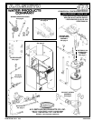
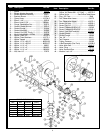
LB/LW 1000 PROPANE GAS TRAIN ASSEMBLY
Item Description Part No.
1 .... Valve, Main Gas, LP 981 Series............. 77780
2 .... Regulator, LP 981 Series ...................... 192460
3 .... Valve, Firing .......................................... 3423-3
4 .... Pipe Plug ................................................ 3348
5 .... Switch, Low Gas Pressure ...................191149-3
6 .... Nipple, 1-1/4” .......................................86505-13
7 .... Nipple, 1-1/4” ....................................... 86505-2
8 .... Nipple, 1-1/4” ...................................... 86505-17
9 .... Elbow, Union 1-1/4” ................................ 86506
Item Description Part No.
10 .... Elbow, 90 Street 1-1/4”.......................... 94516
11 .... Elbow, 90 1-1/4” .................................... 192216
12 .... Nipple, 1-1/4” w/Tapping ..................... 86505-32
13 .... Nipple, 1-1/4” ........................................86505-6
14 .... Nipple, 1-1/4” ...................................... 86505-4
15 .... Tee, 1/8” NPT Branch ............................ 192465
16 .... Connector, Angle 1/8” ............................ 1578
17 .... Bleeder, Tube ........................................ 210016
18 .... Bleeder, Tube ........................................ 192461
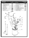
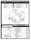
1 ...... Ball Valve ............................................................... 191935
2 ...... Tank/Pump Kit (LW Models Only - Not Shown) ...... 210625
3 ...... Hex Reducing Bushing (LB Only) .......................... 91940-8
4 ...... Flush Bushing (LB Only) .......................................192163-2
5 ...... Relief Valve (LW Model) ........................................ 98883-3
...... Relief Valve (LB Model) .........................................210451-2
6 ...... Strap, Cable (not shown)....................................... 99592-2
7 ...... Tee, Condensate ...................................................192040-1
8 ...... Tee (For use w/relief valve):
............. LW Model ....................................................... 78685-4
............. LB Model ......................................................... 191584
9 ...... Tee 2"x2"x2" .......................................................... 191584
10 ...... Tee 2"x2"x3/4" ...................................................... 78685-4
11 ...... Valve, Drain ............................................................. 26273
12 ...... Valve, Manual Shutoff ............................................. 3423-3
13 ...... Vent Patch Assembly ............................................ 192161
14 ...... Nipple (For use w/Relief Valve)
............. LW Model .......................................................20373-12
............. LB Model ........................................................ 92706-4
15 ...... Clamp, Hose .........................................................191794-1
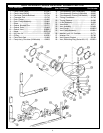
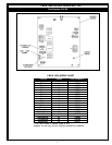
LB/LW 1000 BY-PASS PARTS LIST
Item Description Part No.
On LB models the circulating pump must be between
the boiler inlet and the bypass (see figure below).
LW models have pump mounted inside the jacket.