


3
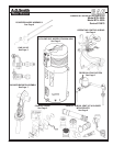
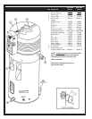
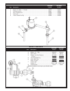
CYCLONE XHE BTH 300A/400A - CONTROL PANEL
BTH 300A BTH 400A
Item Description 974/975 974/975
1 Cable Assembly, Power Switch ................................................................. 194785 ........... 194785
2 Blower Prover Air Switch ........................................................................... 194706 ........... 195013
3 Box, Anode ................................................................................................ 194857 ........... 194857
4 Box, Junction ............................................................................................. 194126 ........... 194126
5 Cable Assembly, Low Voltage ................................................................... 194918 ........... 194918
7 Wire Harness ............................................................................................ 194783 ........... 194783
8 Cable, Assembly - Controls ....................................................................... 194784 ........... 194784
9 Wire Assembly - Air Flow Switch..............................................................192802-2.........192802-2
10 Wire Assembly - Air Flow Switch.............................................................192802-1.........192802-1
Control Board, Cable Assembly (Includes Item 11 & 11A) ........................ 194811 ........... 195018
11 Control Board ......................................................................................... 194812 ........... 195010
11A Cable Assembly ..................................................................................... 194809 ........... 194809
12 Display Board ............................................................................................ 194808 ........... 194808
13 Electronic Control ...................................................................................... 194747 ........... 194747
14 Probe, Upper ............................................................................................. 192606 ........... 192606
15 Probe, Lower ............................................................................................. 192609 ........... 192609
16 Switch, Blocked Inlet ................................................................................. 194911 ........... 195012
17 Switch, Blocked Outlet - NAT .................................................................... 194910 ........... 194910
Switch, Blocked Outlet - LP ....................................................................... 195017 ........... 195017
18 Pump, Recirculation .................................................................................. 196915 ........... 196915
19 Switch, On/Off ........................................................................................... 193243 ........... 193243
20 Switch, NAT, Low Gas Pressure ............................................................191149-6.........191149-6
Switch, LP ,Low Gas Pressure .................................................................191149-4.........191149-4
21 Transformer............................................................................................... 192608 ........... 192608
22 Valve, Natural Gas ...................................................................................194536-5.........194536-5
22 Valve, LP Gas ..........................................................................................194536-6.........194536-6
23 Tubing, 1/4" ID, PVC ................................................................................. 193738 ........... 193738
24 Cable Assembly, Igniter............................................................................. 194937 ........... 194937
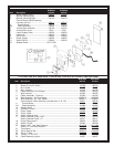
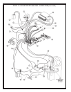
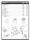
CYCLONE XHE BTH 300A/400A - OPERATING CONTROLS & WIRING (See Next Page)
BTH300A BTH400A
Item Description 974/975 974/975
1 Board, Display Panel ............................ 194808 ........... 194808
2 Bracket, Mounting Left ........................194123-1........ 194123-1
3 Bracket, Mounting Right ....................... 194123 ........... 194123
Control Board, Cable Assembly
(includes 4 & 4A) .................................. 194811 ........... 195018
4 Control Board .................................... 194812 ........... 195010
4A Cable Assembly ................................ 194809 ........... 194809
5 Junction Box Assembly ........................ 194126 ........... 194126
6 Junction Box Cover ................................ 2233 ............... 2233
7 Label, Display Panel ............................. 194203 ........... 194203
8 Label, Led............................................. 194915 ........... 194915
9 Panel Front ........................................... 193884 ........... 193884
10 Screw, Plastic ....................................... 194202 ........... 194202
11 Switch,Off/On ....................................... 193243 ........... 193243
12 Splatter Shield .................................... 197117-000