


3
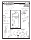
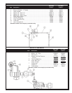
CYCLONE XHE BTH 300A/400A - CONTROL PANEL
BTH 300A BTH 400A
Item Description 970/971 970/971
1 Cable Assembly, Power Switch ..................................................................194785 ............ 194785
2 Blower Prover Air Switch .............................................................................194706 ............ 195013
3 Box, Anode .................................................................................................194857 ............ 194857
4 Box, Junction ..............................................................................................194126 ............ 194126
5 Cable Assembly, Low Voltage ....................................................................194918 ............ 194918
7 Wire Harness ..............................................................................................194783............ 194783
8 Cable, Assembly - Controls ........................................................................194784 ............ 194784
9 Wire Assembly - Air Flow Switch.............................................................. 192802-2 ......... 192802-2
10 Wire Assembly - Air Flow Switch............................................................. 192802-1 ......... 192802-1
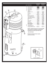
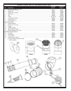
Control Board, Cable Assembly (Includes Item 11 & 11A) .......................... 194811............ 195018
11 Control Board ...........................................................................................194812 ............ 195010
11A Cable Assembly ...................................................................................... 194809............ 194809
12 Display Board .............................................................................................194808............ 194808
13 Electronic Control .......................................................................................194747 ............ 194747
14 Probe, Upper ...............................................................................................196597............ 196597
15 Probe, Lower ...............................................................................................196598............ 196598
16 Switch, Blocked Inlet ..................................................................................194911 ............ 195012
17 Switch, Blocked Outlet - NAT .....................................................................194910 ............ 194910
Switch, Blocked Outlet - LP ........................................................................195017 ............ 195017
18 Pump, Recirculation ....................................................................................194799............ 194799
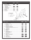
19 Switch, On/Off.............................................................................................193243 ............ 193243
20 Switch, NAT, Low Gas Pressure............................................................. 191149-6 ......... 191149-6
Switch, LP ,Low Gas Pressure ................................................................. 191149-4 ......... 191149-4
21 Transformer .................................................................................................192608 ............ 192608
22 Valve, Natural Gas .................................................................................... 194536-5 ......... 194536-5
22 Valve, LP Gas ........................................................................................... 194536-6 ......... 194536-6
23 Tubing, 1/4" ID, PVC ...................................................................................193738 ............ 193738
24 Cable Assembly, Igniter ..............................................................................194937 ............ 194937
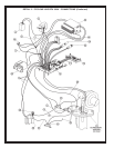
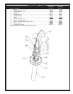
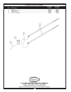
CYCLONE XHE BTH 300A/400A - OPERATING CONTROLS & WIRING (See Next Page)
BTH300A BTH400A
Item Description 970/971 970/971
1 Board, Display Panel ............................ 194808 ............ 194808
2 Bracket, Mounting Left ......................... 194123-1 ......... 194123-1
3 Bracket, Mounting Right........................ 194123 ............ 194123
Control Board, Cable Assembly
(includes 4 & 4A) .................................. 194811 ............ 195018
4 Control Board ..................................... 194812 ............ 195010
4A Cable Assembly ................................ 194809 ............ 194809
5 Junction Box Assembly ........................ 194126 ............ 194126
6 Junction Box Cover ................................. 2233 ............... 2233
7 Label, Display Panel ............................. 194203 ............ 194203
8 Label, Led ............................................. 194915 ............ 194915
9 Panel Front ........................................... 193884 ............ 193884
10 Screw, Plastic....................................... 194202 ............ 194202
11 Switch,Off/On ........................................ 193243 ............ 193243