


Drawing Number:
Drawing Date:
H-6-E
September 07, 2008
NOTE: This drawing is not intended to describe a complete system and is not a replacement for a pro-
fessional engineering drawing. It is intended only as a guide and does not imply compliance with local
building code requirements. Confer with local building officials before installation. The Contractor or
engineer is to determine the necessary components and configuration of the particular system to be in-
stalled. It is the responsibility of the engineer or contractor to ensure that the installation is in accordance
with all local building codes.
23
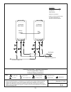
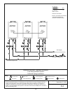
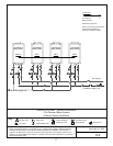
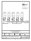
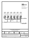
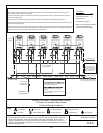
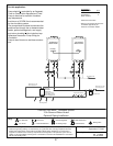
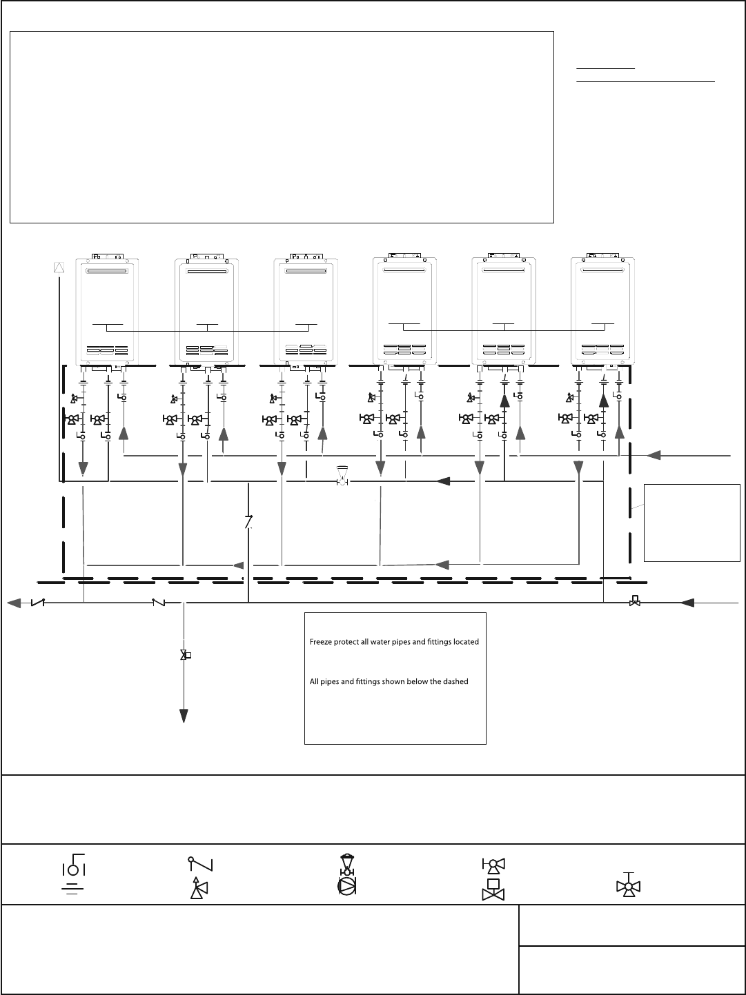
Domestic Hot Water - Optional Freeze Protection
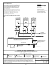
6 Outdoor On-Demand Water Heater
Preferred Piping Installation
On-Demand
Equipment List QTY
On-Demand Outdoor 6
Water Heaters
Electronic Connection *
* Refer to On-Demand Accessories
and Model Applicability for
electronic connection details.
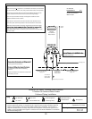
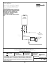
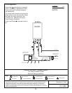
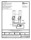
IMPORTANT!
With electrical power supplied to a on-demand water heater, it will not freeze in enviornments as cold as -30
F,
when protected from direct wind exposure.
In the event of a power failure at temperatures below freezing, the water heater should be drained of all water to
prevent freezing damage.
The unit may be drained manually or through the installation of the Optional solenoid valves as shown.
The electrical connections for the two solenoid valves should be tied to the 120V power terminals provided on the
PC Board of the water heater.
When the electrical power to the water heater fails, the cold water supply solenoid valve closes, stopping the ow of
water into the heater, and the drain down solenoid valve opens, allowing the water heater and associated piping to
drain. Ensure that you run the drain for the solenoids per local codes.
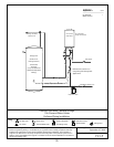
o
Vacuum
Breaker
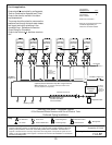
NOTE:
outside building structure. These are indicated
by being above the dashed line.
line should be located inside the building
structure.
The vacuum breaker line should be located inside
the building structure.
Cold Water Supply Line
Gas Supply Line
Route drain
per local codes
Hot Water Supply
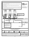
S
Sub 2
Sub 1Pri mary
Sub 2Sub 1Pri mary
S
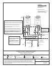
Pressure Regulator
Set to 5 PSI Below
Street Pressure
Outdoor
On-Demand
Water Heater
Outdoor
On-Demand
Water Heater
Outdoor
On-Demand
Water Heater
Outdoor
On-Demand
Water Heater
Outdoor
On-Demand
Water Heater
Outdoor
On-Demand
Water Heater
Normally Closed Solenoid Valve
(Full Size of Cold Water Supply Line)
1/4 “ Minimum
Normally Open
Solenoid Valve
NOTE:
Pipes and ttings can be
installed inside a pipe en-
closure or recess box and
packed with insulation for
additional protection.
Key
Pressure Relief Valve
Check Valve
3/4" Union
3/4" Ball Valve
Boiler Drain Valve
Solenoid Valve
S
Pressure Regulator
Circulating Pump
Mixing Valve