


Drawing Number:
Drawing Date:
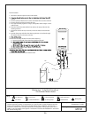
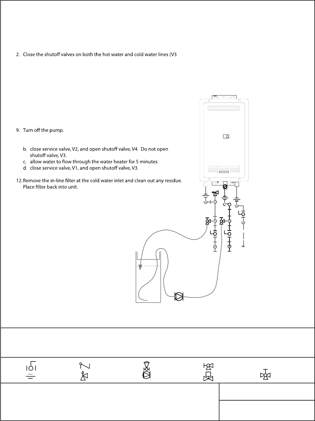
MP-01
September 07, 2008
NOTE: This drawing is not intended to describe a complete system and is not a replacement for a pro-
fessional engineering drawing. It is intended only as a guide and does not imply compliance with local
building code requirements. Confer with local building officials before installation
. The Contractor or
engineer is to determine the necessary components and configuration of the particular system to be in-
stalled. It is the responsibility of the engineer or contractor to ensure that the installation is in accordance
with all local building codes.
38
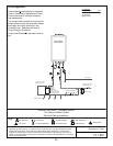
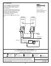
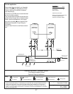
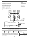
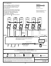
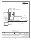
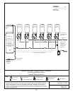
Maintenace - Scale Flush Procedure
1 On-Demand Water Heater
G
a
s
S
u
p
p
l
y
V1
V3
V2
V4
H1
H2
H3
Circulating Pump
C
o
l
d
W
a
te
r
L
in
e
H
o
t
W
a
te
r
L
in
e
In
-
l
ni
e
F
i
l
t
e
r
Flush Procedure
1. Disconnect electrical power to the water heater.
and V4).
3. Connect pump outlet hose (H1) to the cold water line at service valve V2.
4. Connect drain hose (H3) to service valve V1.
5. Pour approximately 4 gallons of virgin, food grade, white vinegar or citric
acid into pail.
6. Place the drain hose (H3) and the hose (H2) to the pump inlet into the
cleaning solution.
7. Open both service valves (V1 and V2) on the hot water and cold water
lines.
8. Operate the pump and allow the cleaning solution to circulate through
the water heater for at least 45 minutes.
10. Rinse the cleaning solution from the water heater by:
a. remove the free end of the drain hose (H3) from the pail
11. Disconnect all hoses.
13. Restore electrical power to the water heater.
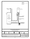
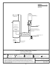
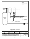
Key
Pressure Relief Valve
Check Valve
3/4" Union
3/4" Ball Valve
Boiler Drain Valve
Solenoid Valve
S
Pressure Regulator
Circulating Pump
Mixing Valve