


16
The unit may be vented horizontally through a wall or vertically through
the roof. Pipe runs must be adequately supported along both vertical
and horizontal runs as follows:
• For Schedule 40, 2" PVC, ABS, Coex Cellular Core vent pipe: Every
3 feet (0.9 m).
• For Schedule 40, 3" PVC, ABS, Coex Cellular Core vent pipe: Every
3.5 feet (1.1 m).
• For Schedule 40, 4" PVC, ABS, Coex Cellular Core vent pipe: Every
4 feet (1.2 m).
• For Schedule 40, 2" CPVC vent pipe: Every 5 feet (1.5 m).
• For Schedule 40, 3" CPVC vent pipe: Every 6 feet (1.8 m).
• For Schedule 40, 4" CPVC vent pipe: Every 6.5 feet (2.0 m).
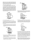
It is imperative that the fi rst hanger (or support) be located on the
horizontal run immediately adjacent to the fi rst 90-degree elbow from
the vertical rise. Support method used should isolate the vent pipe from
the fl oor joists or other structural members to prevent the transmission
of noise and vibration. Do not support, pin, or otherwise secure the
venting system in a way that restricts the normal thermal expansion
and contraction of the chosen venting material.
If the water heater is being installed as a replacement for an existing
power vented heater in pre-existing venting, a through inspection of
the existing venting system must be performed prior to any installation
work. Verify that the correct material as detailed above has been used,
and that the minimum or maximum vent lengths and terminal location
as detailed in this manual have been met. Carefully inspect the entire
venting system for any signs of cracks or fractures, particularly at
the joints between elbows and other fi ttings and the straight runs of
vent pipe. Check the system for signs of sagging or other stresses
in the joints as a result of misalignment of any components in the
system. If any of these conditions are found, they must be corrected
in accordance with the venting instructions in this manual before
completing the installation and putting the water heater into service.
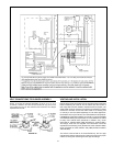
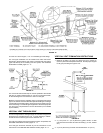
Except where instructed in this manual, the mixing of 2", 3" and 4"
vent pipe is NOT ALLOWED. If 2" pipe is to be used, then a 2" to 3"
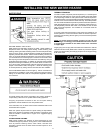
bell reducer is recommended. Figure 15 shows the recommended
location for the bell reducer. If the bell reducer is located at the
rubber boot on the blower assembly, then a short section of 3" vent
pipe needs to be installed in the rubber boot for proper connection of
the 2" to 3" bell reducer. That length can be of the minimum length
required for the connection.
If 4" pipe is to be used, then a 3" to 4" bell reducer is recommended.
Figure 15 shows the recommended location for the bell reducer. If
the bell reducer is located at the rubber boot on the blower assembly,
then a short section of 3" vent pipe needs to be installed in the rubber
boot for proper connection of the 3" to 4" bell reducer. That length
can be of the minimum length required for the connection.
The 40,000, 50,000, 55,000 and 62,500 BTU units are supplied with
a 2" Schedule 40 PVC 22.5° Vent Terminal. If you decide to vent with
3" or 4" pipe, a Schedule 40 DWV 45° Vent Terminal must be used.
For your convenience, we have included a screen for both 3" and 4"
Vent Terminals.
The vent piping should be connected to the blower with a rubber
adapter and secured with hose clamps. The adapter and clamps are
provided with the heater.
Even the flue gas temperature leaving the blower is between
140°F (69°C) and 175°F (79°C), some installations will have water
condensate in the vent piping. If this occurs, then adequate means
of draining and disposing of the condensate needs to be made by
the installer.
CONDENSATE
Condensate formation does not occur in all installations of power vented
water heaters, but should be protected against on installations where it
can form in the venting system. Condensation in the venting system of
power vented water heaters is dependent upon installation conditions
including, but not limited to ambient temperature and humidity of
installation location, ambient temperature and humidity of venting space,
vent discharge and slope, and product usage. In certain conditions,
installations in unconditioned space or having long horizontal or vertical
vent runs may accumulate condensate. In these conditions, the vent
pipe should be sloped downward away from the blower assembly
1/4" (6.4 mm) per fi ve feet (1.5 m) of pipe but not more than 1 1/2" (3.8
cm) in the total vent length. If the vent piping is vented level or sloped
upwards away from the blower assembly, then adequate means for
draining and disposing of the condensate needs to be made by the
installer (if condensate is detected). If you have condensate, then a
3/8" drain hose can be connected to the built-in drain port of the rubber
boot on the blower assembly. For your convenience, the rubber boot
is supplied with a removable cap on the built-in drain port. Prior to
operating the water heater, make sure the removable cap is installed
on the drain port (if a drain hose is not needed).
MAXIMUM AND MINIMUM VENT LENGTHS
40,000 BTU Units:
For 2" Venting, the maximum equivalent feet of pipe allowed is 40
feet (12.2 m). This does not include the supplied vent termination for
the water heater. For the 2" venting, one 90° elbow is approximately
equal to 5 feet (1.5 m). One 45° elbow is approximately equal to 2.5
feet (0.8 m). It is recommended that at least 2 feet (0.6 m) of spacing
be used in between all 45° elbows and all 90°elbows.
For 3" Venting, the maximum equivalent feet of pipe allowed is
120 feet (36.6 m). This does not include the Vent Termination (supplied
locally) for the water heater. For the 3" venting, one 90° elbow is
approximately equal to 5 feet (1.5 m). One 45° elbow is approximately
equal to 2.5 feet (0.8 m). It is recommended that at least 2 feet (0.6 m)
of spacing be used in between all 45° elbows and all 90°elbows.
For 4" Venting, the maximum equivalent feet of pipe allowed is
160 feet (48.8 m). This does not include the Vent Termination (supplied
locally) for the water heater. For the 4" venting, one 90° elbow is
approximately equal to 8 feet (2.4 m). One 45° elbow is approximately
equal to 4 feet (1.2 m). It is recommended that at least 2 feet (0.6 m)
of spacing be used in between all 45° elbows and all 90°elbows.
50,000 BTU Units:
For 2" Venting, the maximum equivalent feet of pipe allowed is 40
feet (12.2 m). This does not include the supplied Vent Termination for
the water heater. For the 2" venting, one 90° elbow is approximately
equal to 5 feet (1.5 m). One 45° elbow is approximately equal to 2.5
feet (0.8 m). It is recommended that at least 2 feet (0.6 m) of spacing
be used in between all 45° elbows and all 90°elbows.
For 3" Venting, the maximum equivalent feet of pipe allowed is
120 feet (36.6 m). This does not include the Vent Termination (supplied
locally) for the water heater. For the 3" venting, one 90° elbow is
approximately equal to 5 feet (1.5 m). One 45° elbow is approximately
equal to 2.5 feet (0.8 m). It is recommended that at least 2 feet (0.6 m)
of spacing be used in between all 45° elbows and all 90°elbows.