


GPVH-40 GPVH-40 GPVR-40 GPVR-40
Item Description 100 101 100 101
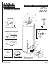
1 ........ Air Intake Screen ............................................................ 9003406.................... 9003406.................... 9003406.................... 9003406
2 ........ Anode, Aluminum - 6 Year .............................................. 9003972.................... 9003972.................... 9003972.................... 9003972
3 ........ Blower Assembly ............................................................ 9004316.................... 9004316.................... 9004316.................... 9004316
4 ............... Blower Assembly Gasket ........................................ ------------ .................... ------------ .................... ------------ .................... ------------
5 ............... Exhaust Adaptor Kit ................................................. 9006020.................... 9006020.................... 9006020.................... 9006020
6 ............... Hose Clamp - 4 inch*** .......................................... ------------ .................... ------------ .................... ------------ .................... ------------
7 ............... Limit Switch** .......................................................... ------------ .................... ------------ .................... ------------ .................... ------------
8 ........ Pressure Switch Kit ........................................................ 9006017.................... 9006017.................... 9006017.................... 9006017
9 ........ Burner Assembly - Natural Gas ..................................... 9005938........................ N/A ........................ 9005940......................... NA
9 ........ Burner Assembly- Propane Gas ........................................ N/A ........................ 9005943........................ N/A ........................ 9005945
10 ....... Burner Head with Door Gasket ................................... ------------.................... ------------.................... ------------ .................... ------------
11 ....... Burner Tube Assembly with Door Gasket ................... ------------.................... ------------.................... ------------ .................... ------------
12 ....... Inner Door with Door Gasket....................................... ------------.................... ------------.................... ------------.................... ------------
13 ....... Orifice, Main Burner with Door Gasket ........................ ------------.................... ------------ .................... ------------ .................... ------------
14 ....... Viewport Assembly ...................................................... ------------.................... ------------.................... ------------ .................... ------------
15 ....... Combination Gas Valve - Natural................................... 9004240........................ N/A ........................ 9004267......................... NA
15 ....... Combination Gas Valve - Propane..................................... N/A ........................ 9005112........................ N/A ........................ 9004464
16 ....... Diffuser Inlet Tube with Spacer ...................................... 9003447.................... 9003447.................... 9003447.................... 9003447
17 ....... Flue Baffle and Restrictor Assembly Kit......................... 9006028.................... 9006028.................... 9006028.................... 9006028
18 ....... FV Sensor and Bracket Kit ............................................. 9006029.................... 9006029.................... 9006029
.................... 9006029
19 ....... Igniter Assy, Hot Surface with Door Gasket.................... 9005958.................... 9005958.................... 9005958....................9005958
20 ....... Inner Door Gasket .......................................................... 9003398.................... 9003398.................... 9003398....................9003398
21 ....... Nipples - 5 inch ..............................................................9003977.................... 9003977.................... 9003977....................9003977
22 ....... Outer Door ...................................................................... 9003545.................... 9003545.................... 9003545....................9003545
23 ....... Thermostat Shield (optional) ......................................... 9005693.................... 9005693.................... 9005693.................... 9005693
24 ....... Turbo Inlet Tube with Spacer..........................................9002067.................... 9002067.................... 9002067....................9002067
25 ....... Valve, Drain - Brass ........................................................ 9004330.................... 9004330.................... 9001870.................... 9001870
26 ....... Valve, T&P Relief ............................................................ 9000071.................... 9000071.................... 9000728....................9000728
27 ....... Vent Terminal Screen Kit ................................................ 9006027.................... 9006027.................... 9006027....................9006027
28 ....... Instruction Sheet - 2, 3 & 4 inch Screens .................... ------------.................... ------------.................... ------------.................... ------------
29 ....... Vent Terminal Screen 2 inch ........................................ ------------.................... ------------.................... ------------.................... ------------
30 ....... Vent Terminal Screen 3 inch ........................................ ------------.................... ------------.................... ------------.................... ------------
31 ....... Vent Terminal Screen 4 inch ........................................ ------------.................... ------------.................... ------------.................... ------------
32 ....... Wire Harness .................................................................9006022.................... 9006022.................... 9006022....................9006022
** Limit Switch located inside control box of blower assembly.
*** Available at local hardware store.
Parts listed without numbers are available as assemblies.
2 of 4
A.O. Smith Water Heater Parts Fulfillment
125 Southeast Parkway • Franklin, TN 37068 • 1-800-433-2525 • www.hotwater.com
PRINTED IN THE U.S.A. 0606 185472-001