


18
Any safety devices including low water cutoffs used in conjunction
with this boiler should receive periodic (every six months) inspection
to assure proper operation. A low water cutoff device of the float
type should be flushed every six months. Periodic checks, at least
twice a year, should be made for water leaks.
More frequent inspections may be necessary depending on water
conditions.
The boiler-mounted gas and electrical controls have been
designed to give both dependable service and long life. However,
malfunction can occur, as with any piece of equipment. It is
therefore recommended that all components be checked
periodically by a qualified serviceman for proper operation.
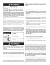
RELIEF VA L VE
The safety relief valve should be opened at least twice a year to
check its working condition. This will aid in assuring proper
pressure relief protection. Lift the lever at the top of the valve
several times until the valve seats properly and operates freely.
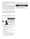
COMBUSTION AIR FIL TER
If the combustion air supply to the boiler contains dust, dirt, drywall
dust etc. a filter must be installed. An air filter is not supplied with the
boiler as shipped from the factory. The installer must provide a filtering
system in the air inlet to the boiler if dust, dirt or construction dirt
can be pulled into the boiler through the inlet air piping. Periodically
clean air filter per the manufacturer's instructions.
BLOWER COMP ARTMENT
The blower compartment should be cleaned annually to remove
any dirt and lint that may have accumulated in the compartment
or on the blower and motor. Buildups of dirt and lint on the blower
and motor can create excessive loads on the motor resulting in
higher that normal operating temperatures and possible shortened
service life.
BURNER MAINTENANCE
Qualified servicers should follow this procedure when the boiler’s
burner needs cleaning.
1. Turn off the electrical power to the boiler and close the main
manual gas shutoff valve(s). Allow the boiler parts to cool before
disassembly.
2. Loosen the flange and separate the gas train from the manifold
assembly.
3. Separate the burner from the blower adapter by first removing
the four (4) bolts and subsequently, the blower gaskets. The
blower should be free to move at this point.
FOR DIRECT VENT UNITS: It is necessary to loosen and slide
the rubber coupling on the blower adaptor in order to move
the blower.
4. Loosen the seven bolts on the blower adapter at the base and
move the burner ground wire (Green) aside.
5. Lift the blower adapter and remove the manifold assembly up
from the 6 studs located on the cover plate and remove the
burner gasket.
6. Remove any loose foreign material such as dust or lint with a
vacuum. Check all ports for blockage. Dislodge any foreign
material causing blockage. Remove any soot or carbon deposits
with a rag making sure to remove any lint left on the burner by
vacuuming again.
7. Reverse the steps to reassemble the unit.
8. Restore electrical power and gas supply to the boiler.
• Put the boiler back in operation by following the Lighting
and Operating instructions in this manual.
• Check for gas leaks and proper boiler and vent operation.
CONDENSA TE REMOVAL SYSTEM
Due to the highly efficient operation of this unit, condensate is
formed during operation and must be removed by the condensate
drain systems. Inspect the condensate drains and tubes at least
once a month and insure they will allow the free flow of condensate
at all times. The system must be inspected more frequently in
cold weather if the drain system is located in an area, such as
along the floor, where freezing temperatures are likely to occur.
The condensate drain system must be protected against freezing.
Contact a qualified service agent to inspect and correct the
condition if freezing of the condensate lines is a problem. The
unit is equipped with a blocked flue switch which will shut the
unit off if condensate is unable to drain and backs up in the
unit. A blocked flue error will appear when sufficient condensate
accumulates for this condition.
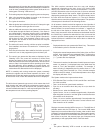
The transparent drain lines and condensate drain on the bottom
of the vent collector should be visually inspected at one month
intervals for blockage, particularly in the areas of the loops in the
lines which trap a small amount of condensate, and the exit point
of the vent collector drain. Condensate in portions of the line other
than the loop area indicates a blockage in the drain line. Flush the