


For full warranty information, refer to the AMX Instruction Manual(s) associated with your Product(s).
8/08
©2008 AMX. All rights reserved. AMX and the AMX logo are registered trademarks of AMX.
AMX reserves the right to alter specifications without notice at any time.
3000 RESEARCH DRIVE, RICHARDSON, TX 75082 • 800.222.0193 • fax 469.624.7153 • technical support 800.932.6993 • www.amx.com
93-2180-05 REV: C
Wiring and Connections
Note: To avoid any damage to the electronic component, installation must be
performed in an ESD safe environment.
Note: Do not connect power to the MET-ECOM-D until the wiring is complete.
After you have completed the installation, consult the Using the Configuration
Manager section of the Metreau Entry Communicators Operation/Reference Guide.
Ethernet 10/100 Base-T RJ-45 Wiring Configuration
The table below describes the pinouts, signals, and pairing for the Ethernet 10/100
Base-T connector and cable.
The MET-ECOM-D uses CAT5/CAT6 wire via the Ethernet port for PoE power.
PoE (Power Over Ethernet)
Use the PS-POE-AF Power over Ethernet Injector (FG423-80) to simplify wiring and
installation by eliminating the need for an AC outlet at each point of installation.
Note: The MET-ECOM-D can be placed up to approximately 330’ (100 meters) from
the PoE Injector.
• If used with a non PoE-capable Ethernet switch (such as the NXA-ENET24),
then an optional PS-POE-AF Power-over-Ethernet (PoE) power supply is
required to provide power to the MET-ECOM-D.
• If the MET-ECOM-D is used with a PoE-capable Ethernet switch (such as the
NXA-ENET24PoE), then no PoE Injectors are required.
Input/Output (I/O) Port: Connections and Wiring
The I/O port responds to either switch closures, voltage level (high/low) changes, or
it can be used for logic-level outputs. A contact closure between the GND and an I/O
port is detected as a Push.
• When used for voltage inputs, the I/O port detects a low signal (0 - 1.5 VDC) as
a Push, and a high signal (3.5 - 5 VDC) as a Release (this IO port uses 5V logic
but can handle up to 12V without harm).
• When used for outputs, the I/O port acts as a switch to GND and is rated for
200 mA @ 5 VDC. This device can use up to 2 I/O ports (see table below).
• The PWR pin provides +5 VDC @ 200 mA.
• The GND connector is a common ground and is shared by all I/O ports (see
table below).
Connecting The Device via I/O
When connecting the I/O port, the GND on the MET-ECOM-D must be connected to
the ground of the I/O device, e.g., a master or any third party I/O device.
Relay Port: Connections and Wiring
You can connect up to 2 independent external relay devices to the Relay connectors
on the MET-ECOM-D.
• Connectors labeled A are for common; B are for output.
• Each relay is isolated and normally open.
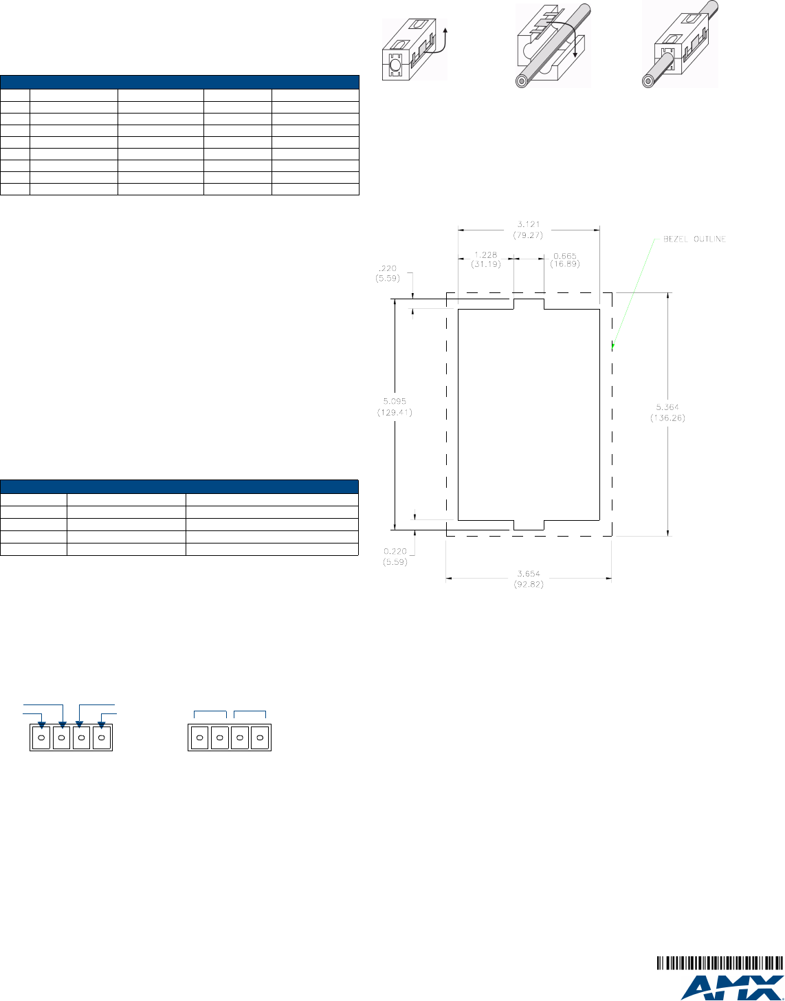
I/O and Relay Connectors - Pinout Configurations
FIG. 3 shows the pin configuration on the I/O and Relay ports.
Note: Do not use the relays on this unit for "secure" applications such as door and
gate releases. For security reasons, an external relay box put in a secure location
will work better for these devices.
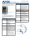
Ferrite Installation (Required)
The MET-ECOM-D comes with a Cat5 Suppression Ferrite that must be clipped
around the Ethernet cable, inside the back box (no tools required).
1. Release the latch to open the plastic enclosure.
2. Insert the Cat5 cable and close the enclosure.
Note: When positioning the Ferrite clip inside the back box, place the bottom of the
clip flat against the back inside surface of the back box, to allow sufficient room for
the MET-ECOM-D unit. See the Operation/Reference Guide for details.
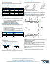
Mounting Specifications
FIG. 5 shows the recommended cutout for the Metreau Entry Communicators Wall
Box. Use these dimensions for wall surface installations using expansion clips..
Note: Refer to the Metreau Entry Communicators Operation/Reference Guide for
additional installation details and drawings.
Positioning the Camera
The Metreau Entry Communicators feature a Camera Viewing Angle Adjustment
slider on the rear panel of the unit that allows you to adjust the viewing angle
horizontally from -15° to 15° (see FIG. 2).
The Camera Viewing Angle Adjustment slider is intended to be used at the time of
installation. It is not intended to be used for regular periodic adjustments. Once a
final installation location has been established, use the Camera Viewing Angle
Adjustment slider to set the desired camera angle, then finalize the installation.
Additional Documentation
Refer to the Metreau Entry Communicators Operation/Reference Guide (available at
www.amx.com) for additional installation/setup details, information on using the
Configuration Manager, the NetLinx module and Programming information.
Ethernet Pinouts and Signals
Pin Signals Connections Pairing Color
1 TX + 1 --------- 1 1 --------- 2 White-Orange
2 TX - 2 --------- 2 Orange
3 RX + 3 --------- 3 3 --------- 6 White-Green
4 no connection 4 --------- 4 Blue
5 no connection 5 --------- 5 White-Blue
6 RX - 6 --------- 6 Green
7 no connection 7 --------- 7 White-Brown
8 no connection 8 --------- 8 Brown
I/O Port Wiring Specifications
Pin Signal Function
15 VDC PWR
2 I/O 2 Input/Output
3 I/O 1 Input/Output
4 GND Signal GND
FIG. 3
I/O and Relay connectors
2
+5V GND
1
BABA
21
Relays
I/Os
1234 1234
FIG. 4
Installing the CAT5 Suppression Ferrite
FIG. 5 Recommended Cutout for Wall Box
123
(complete)