


5. Ener-G-NET
™
Wiring
-5-
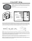
Ener-G-NET incorporates all of the temperature sensing and control necessary for
HYDROMAX™ operation. Built-in switching relays may be wired to operate the boiler
control and circulator pump or zone valve. The diagram below illustrates these internal
switching functions.
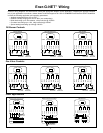
Examples of common wiring scenarios are provided on the following page.
After wiring is complete, insert the white temperature sensor (thermistor) plug into the receptacle at the base of the digital control.
Select the plug marked CIRCULATOR or ZONE VALVE based on the application. Zone valves can be slow actuating. Therefore,
the zone valve sensor contains a built-in temperature offset to account for the time it takes the zone valve to fully close. This results
in potable water temperature that is representative of the digital control temperature set point. This is why it is important to install
the correct sensor into the digital control. See Page 2 for information regarding the selection of a circulator or zone valve.
NOTE: This sensor should not be the primary means of water detection. US PATENT NO: 7,671,754 and other patents pending.
NOTE: Line-voltage and safety-circuit wiring which is external to the water heater jacket when all panels are in place, and which
is part of the appliance, shall be protected by metal conduit, metal-clad cable or raceways. “Power Limited Circuit Cable” needed
not be provided with the protection specified above if it is securely fastened to the appliance jacket and follows the contour of the
appliance jacket. Thermoelectric wiring shall be exempt from this provision.
NOTE: Strain relief shall be provided for all conductors leaving an enclosure. For low-voltage wiring, strain relief at the point of exit
from an enclosure is not necessary if, by wire location or support, protection is provided against accidental strain.
NOTE: For models equipped with a water sensor, the water sensor should be placed flat on the floor in a low-traffic area. On a
regular basis, verify that the water sensor is functioning properly by placing the orange puck in a water puddle or insert a coin
between the two electrodes and listen for audible alarm.
Normally Open
Close on call for hot water
Post-Purge function
Front Panel
Control
Screws (4)
Wiring Cover
Ground Screw
Conduit Holes (3)
Normally Open
Close on call for hot water
Normally Closed
Open on call for hot water
Priority function
Constant 24VAC or 120VAC
Power In
{
{
{
{
ORANGE
ORANGE
BLUE
BLUE
VIOLET
VIOLET
WHITE
BLACK
Water
Sensor Plug
Temperature
Sensor Plug
Water
Sensor