


OPERATION & SERVICE
Servicing should only be performed by a Qualified Service Agent
36
24 VAC Transformer Test
1 Ensure the main breaker or disconnect switch is turned on.
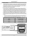
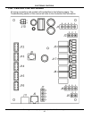
2 Verify with an AC volt meter that proper voltage is present at the Power Distribution Block (see Figure 2 on
page 9 and pages 12-14).
3
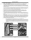
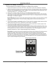
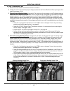
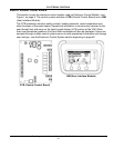
Check Primary Winding Voltage: Using an AC volt meter; set the volt meter to an AC voltage range just
above 120 VAC. With the J1 plug installed in the J1 socket on the CCB (page 42) insert the two volt meter
probes into pins 1 & 3 of the J1 plug as shown in the “Primary Winding Voltage Test” image below. Volt
meter probes may have to be pressed firmly into plug to make contact with the metal conductors inside.
Voltage should be approximately 120 VAC. If the voltage measured is approximately 120 VAC the primary
winding is being powered correctly. If the voltage measured is zero volts or considerably less or more than
120 VAC:
• Check the J1 plug/socket connections on the CCB for wear or damage. Ensure they are mating
properly and providing good contact - see page 42.
• Check the 120 VAC Control Circuit Transformer to ensure it is wired correctly and outputting the
correct voltage - see pages 34 & 35.
• Ensure there is 120 VAC being supplied to the CCB - see page 46.
• Call the toll free technical support phone number on the back cover of this manual for further
assistance if all the procedures above have been performed and 120 VAC is still not present at pins
1 & 3 of the J1 socket/plug on the CCB.
4
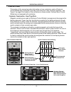
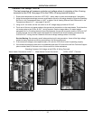
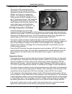
Check Secondary Winding Voltage: Using an AC volt meter; set the volt meter to an AC voltage range
just above 24 VAC. With the J1 plug installed in the J1 socket on the CCB (page 42) insert the two volt
meter probes into pins 4 & 5 of the J1 plug as shown in the “Secondary Winding Voltage Test” image
below. Volt meter probes may have to be pressed firmly into plug to make contact with the metal
conductors inside. Voltage should be approximately 24 VAC. If the voltage measured is approximately 24
VAC the transformer is operating properly. If the voltage measured is zero volts or considerably less than
24 VAC:
• Check the J1 plug/socket connections on the CCB for wear or damage. Ensure they are mating
properly and providing good contact - see page 42.
• Check the wiring between pins 4 & 5 of the J1 plug and the 24 VAC transformer - see Figure 2 on
page 9 for transformer location. Ensure wiring is not pinched or shorted and continuous to the 24
VAC secondary winding - repair or replace damaged wiring as necessary.
• If all the above procedures have been performed and there is still not 24 VAC present at pins 4 & 5
of the J1 plug - replace the 24 VAC transformer. When replacing the transformer check all wiring to
and from the transformer for pinched or shorted wires - repair or replace damaged wiring as
necessary.
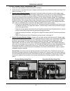
Primary Winding Voltage Test Secondary Winding Voltage Test