


20
correct water column pressure allowing for a nominal pressure
drop through the controls.
The minimum gas supply pressure for input adjustment must not
be less than 4.5" w.c. (1.12 kPa) for natural gas.
Do not subject the combination gas valve to inlet gas
pressures of more than 14.0" W.C. (3.48 kPa) - natural gas.
A service regulator is necessary if higher gas pressures are
encountered.
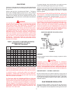
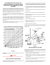
Gas pressure specified in Table 4, refer to flow pressure taken
at pressure tap of automatic gas valve while heater is
operating.
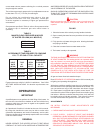
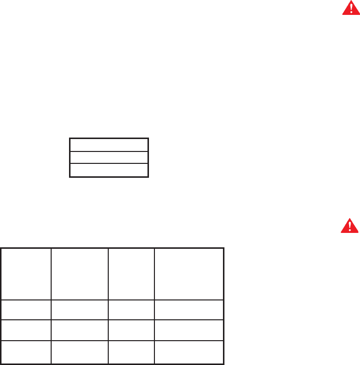
TABLE 8
MANIFOLD GAS PRESSURE IN INCHES
OF WATER COLUMN (ALL MODELS*)
TYPE OF GAS
Natural
3.5 (0.87 kPa)
TABLE 9
APPROXIMATE TIME REQUIRED TO CONSUME
1 CU. FT. OF GAS AT FULL CAPACITY
TIME REQ’D
INPUT TYPE BTUH TO CONSUME
RATE OF PER 1 CU. FT.
(BTUH) GAS CU. FT. OF GAS
154,000 NATURAL 1050 24.5 SEC.
250,000 NATURAL 1050 15.1 SEC.
390,000 NATURAL 1050 9.5 SEC.
Figures shown are valid for 0-2000 ft. installations. See “HIGH
ALTITUDE INSTALLATIONS” for deration requirements over
2000 ft.
OPERATION
IMPORTANT
A qualified person must perform the initial firing of the heater. At
this time the user should not hesitate to ask the individual any
questions which they may have in regard to the operation and
maintenance of the unit.
An Operational Checklist is included at the rear of this manual.
By using this checklist the user may be able to make minor
operational adjustments and avoid unnecessary service calls.
However, the user should not attempt repairs which are not listed
under the USER column.
GENERAL
NEVER OPERATE THE HEATER WITHOUT FIRST BEING
CERTAIN IT IS FILLED WITH WATER AND A TEMPERATURE
AND PRESSURE RELIEF VALVE IS INSTALLED IN THE RELIEF
VALVE OPENING OF THE HEATER.
SHOULD OVERHEATING OCCUR OR THE GAS SUPPLY FAIL
TO SHUT OFF, TURN OFF THE MANUAL GAS CONTROL VALVE
TO THE APPLIANCE.
CAUTION
Before proceeding with the operation of the unit make sure the
water heater and system are filled with water and all air is
expelled.
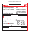
FILLING
1. Close the heater drain valve by turning handle clockwise.
2. Open a nearby hot water faucet to permit the air in the system
to escape.
3. Fully open the cold water inlet pipe valve allowing the heater
and piping to be filled.
4. Close the hot water faucet as water starts to flow.
5. The heater is ready to be operated.
WARNING
THE GAS VALVE MUST HAVE BEEN IN THE OFF POSITION FOR
AT LEAST 5 MINUTES. This waiting period is an important safety
step. Its purpose is to permit gas that may have accumulated in
the combustion chamber to clear. IF YOU DETECT GAS ODOR
AT THE END OF THIS PERIOD DO NOT PROCEED WITH
LIGHTING. RECOGNIZE THAT GAS EVEN IF IT SEEMS WEAK,
MAY INDICATE PRESENCE OF ACCUMULATED GAS
SOMEPLACE IN THE AREA WITH RISK OF FIRE OR
EXPLOSION. SEE THE FRONT PAGE FOR STEPS TO BE TAKEN.
All gas and water lines leak tested and open.
Read SEQUENCE OF OPERATION section of this manual prior
to lighting and operating this appliance.
With above conditions satisfied, start the unit in accordance with
the instructions on the operating label attached to the heater. For
your convenience a copy of the instructions are shown of page
24. Each heater is equipped with an ignition control board. The
controller will try three times to light the main burner before going
into lockout. After the controller tries three times, it will wait one
hour before trying to light the unit again. This cycle will continue
until the main burners are ignited or the unit is shut down.
ADJUSTMENTS
ON INITIAL STARTUP SOME ADJUSTMENTS ARE
NECESSARY.
1. CHECK MANIFOLD AND INLET GAS PRESSURES.
2. CYCLE CHECK - CHECK AT LEAST ONE BURNER
OPERATION - WHEN THERMOSTAT IS SATISFIED, BURNER
WILL SHUT OFF AND INDUCER WILL STOP RUNNING. ON
CALL FOR HEAT - THE INDUCER WILL COME ON AND
CLOSE THE PRESSURE SWITCH AND THE IGNITION
SEQUENCE DESCRIBED ABOVE WILL BEGIN, SEE
“SEQUENCE OF OPERATION”.