


30 www.americanwaterheater.com
D. Inspection, cleaning, priming
Visually inspect the inside of the pipe and fi tting
sockets and remove all dirt, grease or moisture
with a clean dry rag. If wiping fails to clean the
surfaces, a chemical cleaner must be used. Check
for possible damage such as splits or cracks and
replace if necessary.
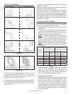
Depth-of-entry
Marking the depth of entry is a way to check if the
pipe has reached the bottom of the fi tting socket
in Step F. Measure the fi tting depth and mark this
distance on the pipe O.D. You may want to add
several inches to the distance and make a second
mark as the primer and cement will most likely
destroy your fi rst one.
Apply primer to the surface of the pipe and fi tting
socket with a natural bristle brush. This process
softens and prepares the PVC or CPVC for the
solvent cementing step. Move quickly and without
hesitation to the cementing procedure while the
surfaces are still wet with primer.
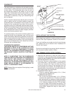
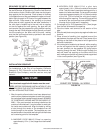
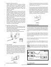
E. Application of solvent cement
• Apply the solvent cement evenly and quickly around
the outside of the pipe at a width a little greater than
the depth of the fi tting socket.
• Apply a light coat of cement evenly around the inside
of the fi tting socket. Avoid puddling.
• Apply a second coat of cement to the pipe end.
STEP E
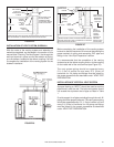
F. Joint assembly
Working quickly, insert the pipe into the fi tting socket
bottom and give the pipe or fi tting a 1/4 turn to evenly
distribute the cement. Do not continue to rotate the
pipe after it has hit the bottom of the fi tting socket.
A good joint will have suffi cient cement to make a
bead all the way around the outside of the fi tting hub.
The fi tting will have a tendency to slide back while
the cement is still wet so hold the joint together for
about 15 seconds.
STEP F
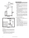
G. Cleanup and joint movement
Remove all excess cement from around the pipe
and fi tting with a dry cotton rag. This must be done
while the cement is still soft.
The joint should not be disturbed immediately after
the cementing procedure, and suffi cient time should
be allowed for proper curing of the joint. Exact drying
time is diffi cult to predict because it depends on
variables such as temperature, humidity and cement
integrity. For more specifi c information, you should
contact your solvent cement manufacturer.
STEP G
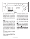
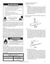
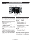
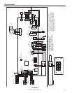
CONNECTION TO VENT PIPE
The vent system connects to the vent pipe with and elbow
or rubber coupling. This coupling includes gear clamps.
These connections must be properly seated and tightened
to prevent the leakage of fl ue gases into the installation
area.
With 2 in. venting the straight rubber adapter is used for the
connection to the vent pipe. With 3 in. venting a transition
adapter is required to change from the 2 in. vent pipe to
the 3 in. vent size.
Clean and lightly sand the end of the vent piping that will
connect to the rubber coupling.
Loosen the upper clamp on the rubber adapter and insert
the sanded end of the vent pipe and tighten the gear
clamp.
NOTE: Do not glue or seal in the rubber coupling. Check
the venting system to ensure that there is no stress on the
connection or the vent pipe which will create a twisting or
bending.
RUBBER COUPLING/
ADAPTER (2”)
RUBBER ADAPTER (2 in.to
3”)
UPPER GEAR
CLAMP
LOWER
GEAR CLAMP
FIGURE 30
U.S. POWER VENT