


TWE-SVX03C-EN 13
Installation
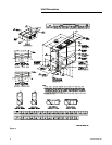
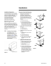
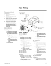
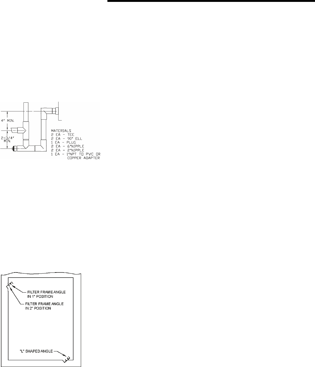
Note: Important! When air handler
is installed in the vertical
position and close proximity
trapping of condensate is
required, use of a subbase
accessory to raise the air
handler for clearance of the
drain trap is recommended.
See Figure 6 for a typical
drain trap assembly
.
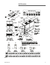
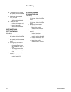
Filters
Air handlers are shipped with
throwaway filters installed. For
replacement filters consult the air
handler service facts for correct size
and number. To replace filters from
the end of the unit, remove lower
access panel (either end) and slide
old filters out and replace with new
ones. To replace from the front of the
unit, remove one "L" shaped angle.
Remove and replace filters and
reinstall "L" shaped angle. See
Figure 7.
.
To convert from 1" filter to a 2" filter
on units so equipped, remove lower
access panels from both ends of the
air handler. Remove screws and
reposition the "L" shaped angles
from both the top and bottom of the
Figure 6.
Figure 7.
filter track to increase the width of the
filter opening.
Duct Connections
The supply and return ducts should
be connected to the unit with flame
retardant duct connectors to reduce
vibration transmission. The return
duct should be sized to the same
dimensions as the return inlet of the
unit.
Note: Important! Duct flanges are
provided for attachment of
the duct work. On TWE060,
090, and 120 the flanges are
not installed but are shipped
inside the air handler. While
facing the air handler with the
control box to your left,
remove the upper access
panel. The duct flanges will
be attached to the belly band
of the air handler nearest
you. Remove the screws
securing flanges in place.
Position the four flanges
around the supply opening.
Secure with field supplied
screws, using the predrilled
holes. On TWE180 and 240,
the duct flanges are packaged
on the outside of the cabinet.
Air Flow Settings
Unit is shipped for nominal airflow
with nominal static pressure. Please
refer to fan performance table in
either the product catalog or unit
service facts and select the proper
drive package for each application.
Failure to do so could result in
improper airflow causing coil
frosting or condensate management
problems. Condensate management
problems such as water drip off or
water blow off could be the result of
too great of air face velocity across
the coil.
ƽ WARNING
Hazardous Voltage
w/Capacitors!
Disconnect all electric power,
including remote disconnects and
discharge all motor start/run
capacitors before servicing. Follow
proper lockout/tagout procedures to
ensure the power cannot be
inadvertently energized. Verify with
an appropriate voltmeter that all
capacitors have discharged. Failure
to disconnect power and discharge
capacitors before servicing could
result in death or serious injury.
Note: For additional information
regarding the safe discharge
of capacitors, see
PROD-SVB06A-EN or
PROD-SVB06A-FR.