


M968255Rev.1.1
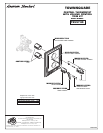
TEMPERATURE ADJUSTMENT
2
WARNING
Prepare water supplies per ROUGHING-IN DIMENSIONS. Make sure the finished wall is between
the minimum and maximum rough dimension.
1
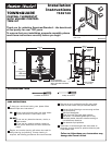
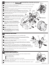
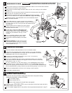
ROUGHING-IN THE VALVE
Install VALVE at indicated height and depth. Make sure the "TOP" marking on the PLASTER
GUARD is up.
Connect the hot and cold water supplies. Assemble all connecting pipes. Flush lines to
remove any dirt. Connections are 1/2" NPT.
Assemble the connection pipe to one of the MIXED OUTLETS of the VALVE.
Cap the other MIXED OUTLET. (Tub port is fitted with a plug at the factory).
IMPORTANT! INSTALL ANY REQUIRED SHUT OFF OR DIVERTER VALVES
INTO THE PIPING SYSTEM.
DO NOT SOLDER DIRECTLY TO THE VALVE BODY; THIS WILL DAMAGE
THE TEMPERATURE CONTROL ELEMENT AND CHECK STOP VALVES.
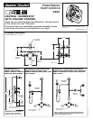
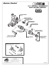
Unscrew PLASTER GUARD SCREWS and remove PLASTER GUARD.
Check that arrow marking B points vertically upwards. If not, push the BLACK
CLAMP on the SECURING RING to the right, pull off KNOB MOUNT and reinstall
KNOB MOUNT with arrow "B" pointing upwards.
For 100 F adjustment, turn the water supply on. Turn KNOB MOUNT until the spout
temperature is 100 F. Check that arrow marking A on the KNOB MOUNT still points
upward after adjusting the thermostat to 100 F. If not, pull out the RED LOCKING DEVICE.
Remove KNOB MOUNT by pulling it towards you while standing directly in front of the valve.
Reinstall the KNOB MOUNT so that the arrow marking A points upwards.
The maximum mixed water temperature is set at 109 F at the factory.
This setting can be changed if desired.
Remove the TEMPERATURE LIMIT STOP (H shaped Black Plastic part). Reinstall it
at the desired notch as indicated in the diagram to limit the maximum mixed water
temperature to 104 F or 112 F.
Reinstall RED LOCKING DEVICE.
KNOB
MOUNT
ARROW
"A"
BLACK
CLAMP
ARROW
"B"
RED LOCKING
DEVICE
SECURING
RING
104
109
112
TEMPERATURE
LIMIT STOP
TOP
CHECK STOP
(HOT RED)
PLUG TUB
PORT
CHECK STOP
(COLD BLUE)
COLD
HOT
1
3
2
4
WOOD
BRACE
5
6
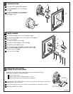
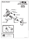
If the CHECK STOPS (4, 5) were removed during installation,
ensure the hot and cold CHECK STOPS (4, 5) are not reversed. The
hot CHECK STOP (4) has a red top and the cold CHECK STOP (5)
has a blue top.
CHECK STOPS (4,5) are supplied in the open position.
Closing using 5/32" (4 mm) hex wrench to pressure
test and to check for leaks.
Reassemble PLASTER GUARD (2) and FINISH
WALL.
Beware of Freezing. No water should remain
in the MIXING VALVE if freezing is a possibility.
Remove the CHECK STOPS (4,5) to completely
drain the MIXER UNIT (1).
Remove PLASTER GUARD (2) if still installed.
Turn on water supplies and check for leaks.
To flush lines, remove the CHECK STOPS (4,5)
and run water. If desired, the TEMPERATURE
CONTROL UNIT can be removed. Reinstall CHECK
STOPS (4,5) and CONTROL UNIT (6), if it was
removed.
HOT
COLD
MIXED
T
OP
PLUG TUB
PORT
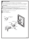
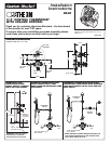
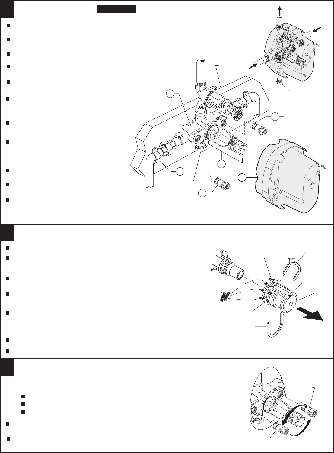
Should the hot and cold water supply pipes have been transposed making
adjustment impossible, proceed as follows:
TRANSPOSED SUPPLY PIPING
OR BACK TO BACK INSTALLATION
3
Remove check stops and re-install them transposed.
Shut off water supply.
Remove handle and rim
CHECK STOP
(RED TO BLUE)
Important note: RED CHECK STOP is now on the right of the mixer body and the BLUE
CHECK STOP is now on the left.
Turn the water supply back on and perform the temperature adjustment in step 2.
CHECK STOP
(BLUE TO RED)