


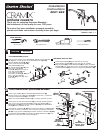

WATER SUPPLY CONNECTIONS
0
1
2
3
4
5
6
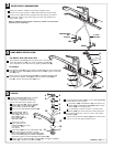
If faucet drips, operate HANDLE (4) several times from
"off" to "on." Do not apply excessive force.
4
3
HAND SPRAY INSTALLATION
5
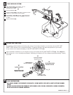
SERVICE
FOR MODELS WITH HAND SPRAY ONLY:
ALL MODELS:
Feed SPRAY HOSE (5) through SPRAY HOLDER (1) and attach COUPLING
NUT (4) of SPRAY HOSE (5) to MOUNTING STUD (3). Tighten COUPLING
NUT (4) firmly.
Make certain that SPACER WASHER (6) and RUBBER WASHER (7)
are attached to SPRAY HOSE (5) and thread SPRAY HEAD (9) to
NUT (8). Tighten COUPLING NUT (8) firmly.
Place SPRAY HOLDER (1) into the appropriate mounting hole,
assemble WING NUT (2) onto shank of SPRAY HOLDER (1)
from underside of sink and secure by tighting WING NUT (2).
M66240 REV.1.1
1
8
9
7
6
2
Note: If additional supply length is required, installer must purchase
additional parts separately.
Bend 3/8” SUPPLY TUBES to meet water supplies valves.
Use palm of hand to support TUBES while bending to avoid kinking.
Connect inlet TUBES to water supplies with appropriate connectors.
Connect left TUBE to HOT water supply, and the right TUBE to the
COLD water supply.
COMPRESSION
NUT
3/8 O.D.
SUPPLIES
FERRULE
COLD
HOT
3
5
1
2
3
4
5
6
7
8
12
13
14
9
10
11
4
AERATOR (14) may accumulate dirt causing distorted
and reduced water flow. Remove, clean, and replace
AERATOR (14).
Clogged CARTRIDGE (1) inlets or outlets
may cause reduced flow in "full on,"
hot or cold. To clean ports, first turn
off Hot and Cold water supplies, then:
Remove BUTTON (2), loosen HANDLE
SCREW (3) and pull HANDLE (4) off.
Remove ESCUTCHEON CAP (5).
Lift CARTRIDGE (1) off
MANIFOLD (7), remove
SEALS (8). Clean ports,
SEALS (8), FLOW
REGULATOR (9) and
MANIFOLD (7).
If hand spray water
flow is restricted, lift
DIVERTER (10) using long-
nose pliers. Clean
and replace.
Replace ESCUTCHEON CAP (5), HANDLE (4), and tighten HANDLE
SCREW (3). Replace PLUG BUTTON (2).
To replace SPOUT SEALS (11), remove CARTRIDGE (1)
as described on the left, then:
Remove three MOUNTING SCREWS (6).
Insert SEALS (8) back into CARTRIDGE (1).
Make certain larger diameter of FLOW
REGULATOR (9) faces inside CARTRIDGE (1).
Place CARTRIDGE (1) onto MANIFOLD (7) and
alternately tighten the three MOUNTING SCREWS (6).
Slip SPOUT (12) off MANIFOLD (7) and replace LIP
SEALS (11) and BEARING RING (13). Make certain
SEALS (11) are well lubricated.
For assembly, proceed as above in reverse order.