


M968699 Rev. 1.10
7
9
6
2
1
5
8
10
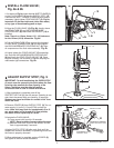
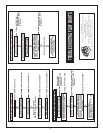
121mm,+13mm, -6mm
(4-3/4)(+1/2, -1/4)
Fig. 8b
5
Fig. 9
2
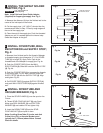
REMOVE COVER
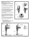
CLOCKWISE CLOSES
CONTROL STOP
COUNTER-CLOCKWISE
OPENS CONTROL STOP
IMPORTANT: To avoid overflowing, the SUPPLY STOP
(3) must never be opened to the point where the flow
from the valve exceeds the flow capacity of the
fixture. The fixture must be able to handle a
continuous flow in case of a flush valve failure.
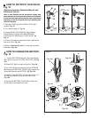
1. After installation is complete, peel off the
PROTECTIVE FILM (1) from the sensor. Standing to one
side, block the sensor with your hand for 10 seconds.
Remove your hand and listen for audible “click” from
within the valve.
2. Remove COVER (2) from SUPPLY STOP (3).Turn on
water supply 1/4 turn to 1/2 turn(CCW) and test for
leaks. Note: Unit may flush for approximately 5 to 10
sec. when water is first turned on. If flow persists,
turn water off and repeat step #1 above.
3. Actuate the FLUSH VALVE:
A) Cover sensor with hand for 10 seconds.
NOTE: Stand outside of sensor detection aera.
B) Remove hand from in front of the sensor; unit will
flush in approximately 3 seconds.
4. Adjust SUPPLY STOP (3) after each flush until the
stated flush volume is achieved, no splashing occurs and
the fixture is properly cleansed.
5. When adjustment is complete, replace COVER (2)
and tighten to ensure vandal-resistance.
ADJUST SUPPLY STOP; Fig. 9
7
3
Fig. 8a
3
2
5
1
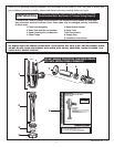
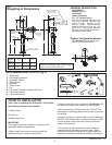
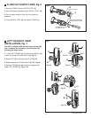
1. As shown in Fig. 8a, insert the side INLET FLANGE (1)
on the FLUSH VALVE (2) into the SUPPLY STOP (3).
Lubricate the INLET FLANGE O-RING (4) with water if
necessary. Lightly tighten COUPLING NUT (5). Fig. 8a.
Important: Do not use lubricants (other than water)
or any type of thread sealing paste or tape.
2. Align the FLUSH VALVE (2) (Fig. 8b) directly above
the DOWN TUBE (7) and VACUUM BREAKER
COUPLING NUT (6). Make sure that GASKET (10) is
installed.
Note: There is a +13mm, -6mm (+1/2, -1/4) tolerance
for the 121mm (4-3/4) dimension. Fig. 8b.
3. Pull the DOWN TUBE (7) up to meet the threaded
FLUSH VALVE CONNECTION (8) and hand tighten
the VACUUM BREAKER COUPLING NUT (6). Align
all components of the flush valve assembly. Fig. 8b.
4. Lightly tighten the COUPLING NUT (5) connection
first, then the VACUUM BREAKER COUPLING NUT
(6) and finally the SPUD COUPLING NUT (9). Once
alligned correctly, use a wrench to tighten couplings to
make water tight connections. Fig. 8b.
INSTALL FLUSH VALVE;
Fig. 8a & 8b
6
4