


3
Fig. 2
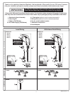
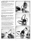
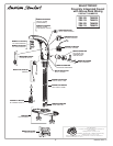
MAKE WATER SUPPLY
CONNECTIONS; Fig. 2
3
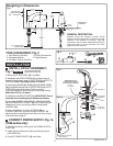
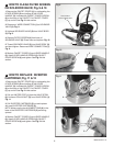
INSTALL OPTIONAL MIXING
VALVE; Fig. 3
4
1. Turn off hot and cold water supplies before
beginning.
2. Connect HOSE ADAPTERS (3) to wall supplies (if
required). Connect FLEXIBLE SUPPLIES (1, 2) directly
to HOSE ADAPTERS (3).
3. Connect left supply (Marked with a Red Stripe) to
Hot and right supply (Marked with Blue Stripe) to Cold
supply. Use adjustable
wrench to tighten connections. Do not over tighten.
4. Faucet supplies are 18" long from faucet base.
Note; If additional supply length is required,
installer must purchase those parts separately.
Important; If SUPPLY HOSES (1, 2) are too long,
loop as illustrated to avoid kinking.
Fig. 3
Fig. 1
M965255 REV. 1.6
1
2
3
COLD
HOT
Note; For complete detailed installation and
operating instructions see installations
instructions supplied with mixing valve.
No. M968808
For 7055.105/115 & 7056.105/115 Faucets.
Installation Instructions
Installation Instructions
(In Toronto Area only: 1-905-3061093)
SELECTRONIC™
Thermostatic Mixing Valve
Certified to comply with ASME A112.18.1M
© 2005 American Standard
M968808
To l e a rn m or e a b o ut A m e ri c a n S ta n d ar d F au c e ts v is i t o u r w eb s i te at : www.us.amstd.com or U.S.
customer's e-mail us at: faucetsupport@amstd.com
For Parts, Service, Warranty or other Assistance,
please call
1-800-442-1902 (In Canada: 1-800-387-0369)
NOTE TO INSTALLER: Please give this manual to the customer after installation.
(In Toronto Area only: 1-905-3061093)
605XTMV
Specications
Installation
Adjust Temperature
Service
Replacement Parts
1
2
3
3
4
No. M968808
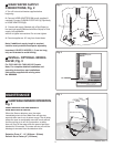
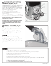
MAINTENANCE
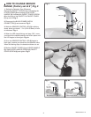
When the Sensor detects a user, the water
immediately starts to flow. Water flow will stop two
seconds after user is out of sensor range. The off delay
allows the user to comfortably move his hands without
the flow cycling on to off. As a precaution, a safety
timer will turn off the water, after the sensor has been
blocked for 59 seconds. The water will stay off until the
blockage is removed from the detection zone.
Detection Zone: 2" - 10" (50.8mm - 254mm)
Default: Set at Factory 6" (152.4mm)
HAND WASH SENSOR OPERATION;
Fig. 1
1
DETECTION
ZONE
REMOVE PROTECTIVE FILM FROM SENSOR EYE
WHEN INSTALLATION IS COMPLETE.
PROTECTIVE FILM
SEAL
WASHER
(SUPPLIED)