


4
Fig. 3
Fig. 2
M965255 REV. 1.6
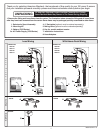
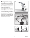
1. Setting the Detection Zone (Distance):
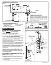
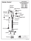
Remove the FAUCET COVER (1) by unthreading the
LEVER SCREW (2) and pulling off the LEVER
HANDLE (3). Unthread the FAUCET COVER SCREW
(4) at the back of the FAUCET. Pull FAUCET COVER
(1) up and off. Fig. 2.
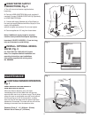
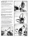
2. Disconnect the BLACK POWER SUPPLY
CONNECTOR (1) and reconnect. Fig. 3.
3. While the SENSOR CONTROL LED (2) is blinking
slowly, place your hand 1 - 2 in. (25.4-50.8mm) in front
of the sensor. Fig. 4.
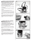
4. When the LED stops blinking and stays "ON", move
your hand to the desired position and hold in place until
the LED begins to blink again. Fig. 4a.
5. Once the SENSOR CONTROL LED (2) begins to
blink again, remove your hand from the detection zone.
When the flashing stops, the detection distance is set.
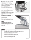
6. Replace FAUCET COVER (1) and LEVER HANDLE
(3). Install LEVER HANDLE SCREW (2), FAUCET
COVER SCREW (4) and tighten. Fig. 2.
HOW TO CHANGE SENSOR
RANGE; (Factory set at 6") Fig. 2
2
1
1
4
3
2
Fig. 4 Fig. 4a
UP TO 10"
(254mm)
BLINKING LED
REMOVE
REPLACE
2
BLINKING LED
2
1"-2"
(25.4mm-
50.8mm)