


1
1
3
5
2
4
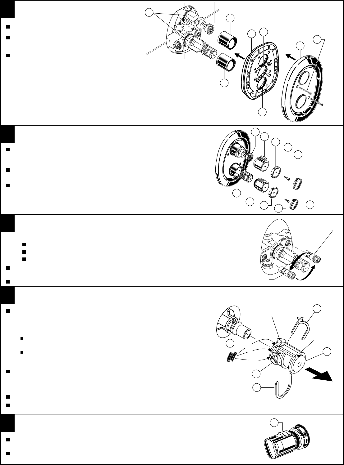
TEMPERATURE CALIBRATION
SET HOT LIMIT STOP
5
Check that arrow marking B points vertically upwards. If not, push the BLACK
CLAMP (1) on the SECURING RING (2) to the right, pull off KNOB MOUNT (3)
and reinstall KNOB MOUNT (3) with arrow "B" pointing upwards.
For 100 F adjustment, turn the water supply on. Turn KNOB MOUNT (3) until the spout
temperature is 100 F. Check that arrow marking A on the KNOB MOUNT (3) still points
upward after adjusting the thermostat to 100 F. If not, pull out the RED LOCKING DEVICE (5).
Remove KNOB MOUNT (3) without turning by sliding out as indicated by the arrow.
Reinstall the KNOB MOUNT (3) so that the arrow marking A points upwards.
The maximum mixed water temperature is set at 109 F at the factory.
This setting can be changed if desired.
Remove the TEMPERATURE LIMIT STOP (4) (H shaped Black Plastic part).
Reinstall it at the desired notch as indicated in the diagram to limit the maximum
mixed water temperature to 104 F or 112 F.
Reinstall RED LOCKING DEVICE (5).
ARROW
"A"
ARROW
"B"
104
109
112
OPERATING THE VALVE
4
1
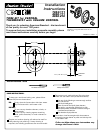
Push CAPS (1) over the O-RING SEALS (2).
TRIM INSTALLATION
Push on ESCUTCHEON (5) and attach with (60mm)
SCREWS (6) to valve body.
100
If a temperature over 100 F is desired, pull the RED STOP BUTTON (1) away from the body
of the MIXER UNIT and turn the TEMPERATURE KNOB.
If the system is delivering all Hot or all Cold and no mixed water the pipes are probably transposed.
This will increase the mixed water temperature up to the maximum limit previously
selected in step 4.
Push ESCUTCHEON HOLDER (3) with lightly greased
O-RING SEAL (4) over CAP (1).
2
1
3
1
2
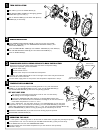
HANDLE INSTALLATION
Push TEMPERATURE-CONTROL KNOB (1) with the red stop onto KNOB
MOUNT (2). Push RING (3) onto TEMPERATURE-CONTROL KNOB (1) and
attach with SCREW (4).
Push VOLUME-CONTROL KNOB (6) onto HANDLE ADAPTER (8). Push RING (3)
onto VOLUME-CONTROL KNOB (6) and and attach with SCREW (7).
Press on KNOB CAPS (5).
50
60
T
O
P
/
O
P
E
N
4
8
3
3
4
5
6
1
2
7
5
4
6
5
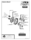
Should the hot and cold water supply pipes have been transposed making
adjustment impossible, proceed as follows:
TRANSPOSED SUPPLY PIPING OR BACK TO BACK INSTALLATION
3
Remove check stops and re-install them transposed.
Shut off water supply.
Remove handle and rim
CHECK STOP
(RED TO BLUE)
Important note: RED CHECK STOP is now on the right of the mixer body and the BLUE
CHECK STOP is now on the left.
Turn the water supply back on and perform the temperature adjustment in step 4.
CHECK STOP
(BLUE TO RED)
M968417 REV 1.1