


M968617 Rev.1.2
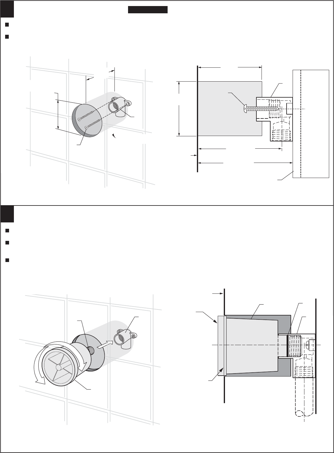
2
INSTALL PLASTER GUARD
3
FINISHED WALL
REMOVE
MINIMUM
(LINE MARK)
MAX.
(LINE MARK)
2
1
INSTALL
Make sure the O-RING (3) is installed on the PLASTER GUARD (1).
Install the PLASTER GUARD (1) into ELBOW (2). Note: The finished wall must be between the Min. & Max.
lines on the PLASTER GUARD (1).
Complete all tiling and wall work. When walls are finished remove PLASTER GUARD (1).
1
CAUTION
Turn off hot and cold water
supplies before beginning.
1
INSTALL SUPPLY PIPING
Provide a “Installation Hole” 2-1/8" - 2-3/8" DIA., (54-60mm) and 3-1/4", (83mm) deep. Note: The “Installation Hole”
must be clear to allow body spray clearance.
Install the ELBOW (1) on a support within the wall at the *dimension shown. Secure with
two M5 SCREWS (2) (not provided).
FINISHED WALL
WALL SUPPORT
54-60mm
(2-1/8" - 2-3/8" DIA.)
1
2
83mm
(3-1/4")
54-60mm
(2-1/8" - 2-3/8" DIA.)
*63.6-70.6mm
(2-1/2" - 2-3/4")
82.6mm
(3-1/4")
*75.6-82.6mm
(2-15/16" - 3-1/4")
2
1
2
3
“Installation Hole”
“Installation Hole”
{