


12
INLET/OUTLET VENT TERMINATIONS (175,000+ BTU/HR)
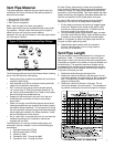
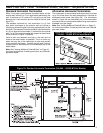
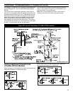
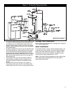
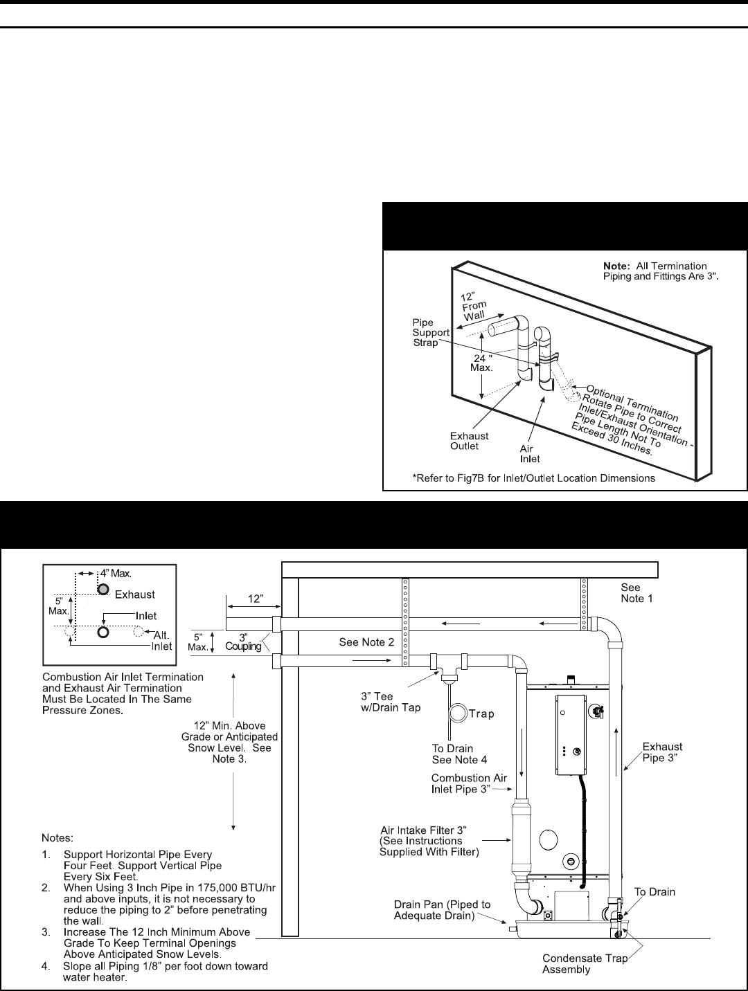
Figure 8B: Alternative Horizontal Termination
(175,000+ BTU/Hr or greater input models)
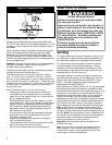
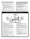
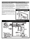
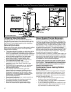
Figure 7B: Standard Horizontal Termination (175,000+ BTU/Hr models)
Standard Horizontal Termination
The standard horizontal air inlet termination is a 3 inch
pipe which terminates at the exterior wall and utilizes a
coupling to prevent the pipe from being pushed back into
the structure. The standard horizontal exhaust outlet termi-
nation is a 3 inch pipe which terminates 12 inches from the
outside wall. The air inlet must be located with respect to
the exhaust outlet as shown in figure 7B (bottom).
Install a 3 inch coupling at the outside wall on both the inlet
and exhaust to prevent the terminations from being pushed
inward.
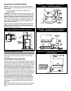
Install a drain tee assembly and trap in the inlet vent as
close to the water heater as possible. This is to drain any
water that may be in the combustion air pipe and prevent it
from entering the blower. Connect the trap drain line to a
suitable drain or downstream of the condensate trap of the
water heater.
Note: See “Venting Additional Polaris® Units” on Page 13
for correct terminations if installing more than one Polaris®
gas water heater.
Alternative Horizontal Termination
The combustion air and exhaust terminations may be
raised up to 24 inches above the wall penetrations if
required for anticipated snow levels (see figure 8B). The
two elbows shown in figure 8B are considered part of the
termination and should not be included when determining
the maximum allowable vent pipe length.
Note: See “Venting Additional Polaris® Units” on Page 13
for correct terminations if installing more than one Polaris®
gas water heater.
*100 Gallon Model Shown.