


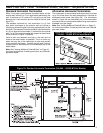
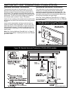
8
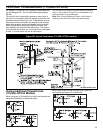
Vent Termination Locations
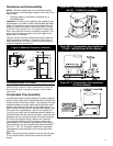
The air inlet and exhaust outlet must be installed with the
following minimum clearances (see figure 6):
• Twelve inches above grade or maximum anticipated
snow level.
• Twelve inches from any opening through which flue
gases could enter the structure.
• Four feet horizontally and vertically from gas or electric
meters, gas regulators, dryer vents, vent hoods, bath-
room fan exhaust, attic fans and turbines.
• Two feet from an inside corner formed by two exterior
walls.
• Two feet from porches, decks, overhangs and other
obstructions.
In addition to maintaining the minimum clearances , the
vent should terminate according to the following guidelines:
1. Use only 2 inch pipe or a 2 inch concentric vent on
the vent termination for 100,000 - 150,000 BTU/Hr
models. For inputs of 175,000 BTU/Hr or more, use
only 3 inch pipe or a 3 inch concentric vent. Do not
expose any 3” X 2” reducers or bushings to out-
door ambient temperatures.
2. The air inlet and exhaust outlet must not terminate
under a patio, deck or any covered area.
3. Do not terminate the vent near walkways or into alleys
or other publicly accessible areas.
4. Do not terminate the vent in an area where children
or animals could block pipes.
5. Do not locate the vent terminal too close to shrubs or
bushes.
6. Caulk all cracks, seams and joints within 6 feet horizon-
tally above and below the vent.
7. Combustion air inlet termination and exhaust air termi-
nation must be located in the same pressure zone.
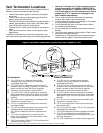
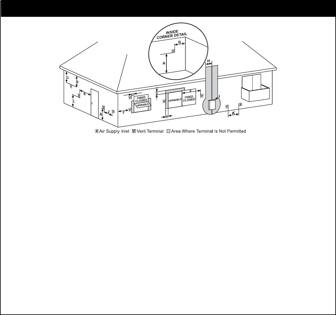
Figure 6: Minimum Clearances for Inlet/Outlet and Concentric Vent
A. 12 in (30 cm) min. clearance above grade,
veranda, porch, deck, balcony, or maximum
anticipated snow level.
B. 12 in (30 cm) min. clearance on top and side of
window or door that may be opened. Do not install
below a window or door that may be opened.
C. Clearance to permanently closed window.**
D. 12 in (30 cm) min vertical clearance to ventilated
soffit located above the terminal within a horizontal
distance of 2 ft (61 cm) from the center line of the
terminal.
E. 12 in (30 cm) min. clearance to unventilated soffit.
F. Clearance to outside corner **
G. 2 ft (61 cm) clearance to inside corner formed by
two exterior walls.
H. 4 ft (122 cm) clearance to each side of center line
extending above meter/regulator assembly.
I. 4 ft (122 cm) clearance to service regulator vent
outlet.
J. 12 in (30 cm) clearance to nonmechanical air
supply inlet to building or the combustion air inlet
to any other appliance.
K. 3 ft (91 cm) above if within 10 ft (3 m) horizontally of
mechanical air supply inlet.
**Clearance in accordance with local installation codes and the requirements of the gas supplier.
A. 12 in (30 cm) min. clearance above grade,
veranda, porch, deck, balcony, or maximum
anticipated snow level.
B. 12 in (30 cm) min. clearance on top and side of
window or door that may be opened. Do not install
below a window or door that may be opened.
C. Clearance to permanently closed window.**
D. 12 in (30 cm) min vertical clearance to ventilated
soffit located above the terminal within a horizontal
distance of 2 ft (61 cm) from the center line of the
terminal.
E. 12 in (30 cm) min. clearance to unventilated soffit.
F. Clearance to outside corner. **
G. 2 ft (61 cm) clearance to inside corner formed by
two exterior walls.
H. 3 ft (91 cm) within a height 15 ft (4.57 m) above the
meter/regulator assembly.
I. 4 ft (122 cm) clearance to service regulator vent outlet.
J. 12 in (30 cm) clearance to nonmechanical air
supply inlet to building or the combustion air inlet to
any other appliance.
K. 6 ft (1.83 m) clearance to mechanical air supply inlet.
US Installations Canadian Installations