


32
O
PERATIONAL
C
HECKS
& S
AFETY
C
IRCUIT
D
ESCRIPTION
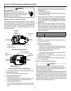
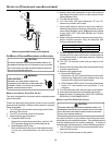
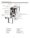
ROLLOUT LIMITS
The rollout limit controls are mounted on the burner/manifold
assembly and monitor the burner flame. They are manual-
reset, temperature sensors. This limit guards against burner
flames not being properly drawn into the heat exchanger.
PRESSURE S WITCHES
The pressure switches are normally-open, negative air pres-
sure-activated switches. They monitor the airflow (combustion
air and flue products) through the heat exchanger via pressure
taps located on the induced draft blower. These switches guard
against insufficient airflow (combustion air and flue products)
through the heat exchanger.
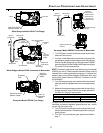
FLAME S ENSOR
The flame sensor is a probe mounted to the burner/manifold
assembly which uses the principle of flame rectification to de-
termine the presence or absence of flame.
T
ROUBLESHOOTING
ELECTROSTATIC D ISCHARGE (ESD) PRECAUTIONS
NOTE: Discharge body’s static electricity before touching unit.
An electrostatic discharge can adversely affect electrical
components.
Use the following precautions during furnace installation and
servicing to protect the integrated control module from dam-
age. By putting the furnace, the control, and the person at the
same electrostatic potential, these steps will help avoid expos-
ing the integrated control module to electrostatic discharge.
This procedure is applicable to both installed and uninstalled
(ungrounded) furnaces.
1. Disconnect all power to the furnace. Do not touch the
integrated control module or any wire connected to the
control prior to discharging your body’s electrostatic
charge to ground.
2. Firmly touch a clean, unpainted, metal surface of the
furnace away from the control. Any tools held in a
person’s hand during grounding will be discharged.
3. Service integrated control module or connecting wiring
following the discharge process in step 2. Use caution
not to recharge your body with static electricity; (i.e., do
not move or shuffle your feet, do not touch ungrounded
objects, etc.). If you come in contact with an ungrounded
object, repeat step 2 before touching control or wires.
4. Discharge your body to ground before removing a new
control from its container. Follow steps 1 through 3 if
installing the control on a furnace. Return any old or
new controls to their containers before touching any
ungrounded object.
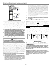
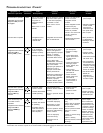
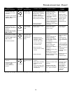
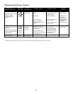
DIAGNOSTIC C HART
Refer to the troubleshooting chart in the Appendix for assis-
tance in determining the source of unit operational problems.
The red diagnostic LED blinks to assist in troubleshooting the
unit. The number of blinks refer to a specific code.
NOTE: To clear all alarm codes, depress the push button for 6
seconds.
FAULT R ECALL
The ignition control is equipped with a momentary push button
switch that can be used to display on the diagnostic LED the
last five faults detected by the control. The control must be in
Standby Mode (no thermostat inputs) to use the feature. De-
press the pushbutton switch for approximately 2 seconds. Re-
lease the switch when the LED is turned off. The diagnostic
LED will then display the flash codes associated with the last
five detected faults. The order of display is the most recent fault
to the least recent fault.
RESETTING F ROM L OCKOUT
Furnace lockout results when a furnace is unable to achieve
ignition after three attempts. It is characterized by a non-func-
tioning furnace and a one flash diagnostic LED code from the
red LED. If the furnace is in “lockout”, it will (or can be) reset in
any of the following ways.
1. Automatic reset. The integrated control module will
automatically reset itself and attempt to resume normal
operations following a one hour lockout period.
2. Manual power interruption. Interrupt 115 volt power to
the furnace for 1 - 20 seconds.
3. Manual thermostat cycle. Lower the thermostat so that
there is no longer a call for heat for 1 - 20 seconds then
reset to previous setting.
NOTE: If the condition which originally caused the lockout still
exists, the control will return to lockout. Refer to the Diagnostic
Chart for aid in determining the cause.
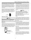
M
AINTENANCE
T
O
AVOID
ELECT RICAL
SHOCK
,
INJURY
OR
DEATH
,
DISCONNECT
ELECT RICAL
POWER
BEFORE
PERFORMING
ANY
MAINTENANCE
.I
F
YOU
MUST
HANDLE
THE
IGNITER
,
HANDLE
WITH
CARE
.T
OUCHING
THE
IGNITER
ELEMENT
WITH
BARE
FINGERS
,
ROUGH
HANDLING
,
OR
VIBRATION
COULD
DAMAGE
THE
IGNITER
RESULTING
IN
PREMATURE
FAILURE
.O
NLY
A
QUALIFIED
SERVICER
SHOULD
EVER
HANDLE
THE
IGNITER
.
WARNING