


5
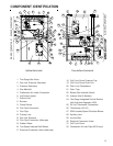
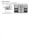
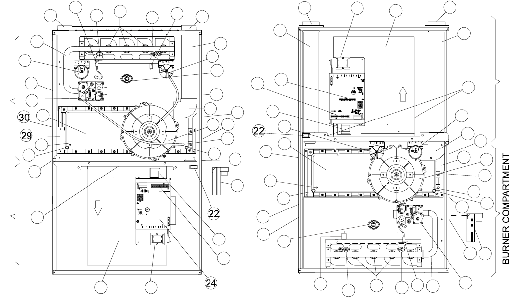
COMPONENT IDENTIFICATION
Counterflow /HorizontalUpflow/Horizontal
1 Two-Stage Gas Valve
2 Gas Line Entrance (Alternate)
3 Pressure Switch(es)
4 Gas Manifold
5 Combustion Air Intake Connection
6 Hot Surface Igniter
7 Rollout Limit
8 Burners
9 Flame Sensor
10 Flue Pipe Connection
11 Flue Pipe
12 Primary Limit
13 Gas Line Entrance
14 Flue Pipe Connection (Alternate)
15 Rubber Elbow
16 Two-Speed Induced Draft Blower
17 Electrical Connection Inlets (Alternate)
18 Coil Front Cover Pressure Tap
19 Coil Front Cover Drain Port
20 Drain Line Penetrations
21 Drain Trap
22 Blower Door Interlock Switch
23 Inductor (Not All Models)
24 Two-Stage Integrated Control Module
(with fuse and diagnostic LED)
25 24 Volt Thermostat Connections
26 Transformer (40 VA)
27 ECM Variable Speed Circulator Blower
28 Auxiliary Limit
29 Junction Box
30 Electrical Connection Inlets
31 Coil Front Cover
32 Combustion Air Inlet Pipe (ACV9 only)
BLOWER COMPARTMENT
1
9
7
8
7
4
6
12
13
21
20
19
18
31
3
24
23
25
32
5
26
27
10
28
3
15
14
16
18
19
20
2
11
17
30
29
BLOWER COMPARTMENT BURNER COMPARTMENT
1
2
3
4
5
6
7
8
7
9
10
11
3
12
13
14
15
16
18
19
20
23
25
26
27
28
21
20
19
18
31
17
Intell-I
g
nition
*
*
*
*
*
*
*
*
*