


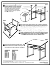
Insert two rear extension tubes (
E) at rear of frame
as shown in Figure 3.
Curved black caps on tubes
should be set into frame so inclines face front and
back of frame. Carefully insert two front extension
tubes (
F) with attached brackets facing out. All
four extension legs should be at their lowest
position and locked with four height adjustment
knobs (H). Set base aside.
Place tabletop (
B
) with preferred side facing down on carpeted or protected floor.
Place supplied cardboard template on board surface with edge of template at front
edge of board. Left and right edges of template should be an equal distance from
each side of the tabletop. Using a
1
⁄
8
" drill bit, gently drill ¼" deep holes where
marked on the template.
Remove template.
Wrap masking tape ¼" from drill bit end to determine drilling depth. Take care to
drill only ¼" deep to avoid drilling through and destroying tabletop surface.
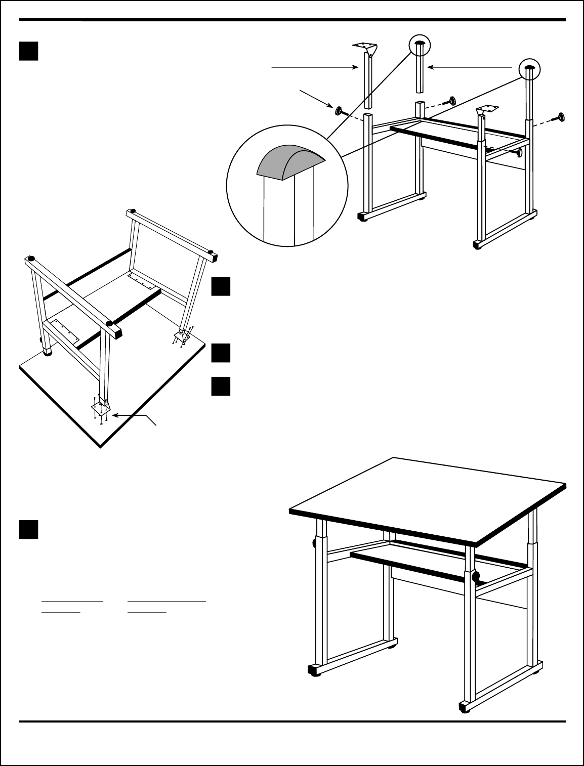
Carefully return table assembly to the upright position. Adjust
tabletop to desired height using height adjustment knobs (
H).
You’re finished and your table is ready to use
(see Figure 5).
Figure 3
Figure 4
Figure 5
Adjustment knob
Front extension tube
Rear extension tube
5
⁄
8
" Screws
Carefully turn table assembly upside down and place on top of tabletop. Align holes
in front leg extension brackets (
F) with holes in tabletop
(see Figure 4). Fasten all
5
⁄
8
" screws (I) and tighten securely. Use care not to overtighten and strip.
7
8
9
TIP
10
WORKMASTER
MODELS:
WM48-3-XB
WM48-4-XB
WM60-3-XB
WM60-4-XB
WM72-3-XB
WM72-4-XB
WORKMASTER JR.
MODELS:
WMJ-3-XB
WMJ-4-XB
WMJ48-3-XB
WMJ48-4-XB
WMJ-3-WBR
WMJ-4-WBR
WMJ-3-XBR
WMJ-4-XBR
©2007
ALVIN & COMPANY, INC. • P.O. Box 188, Windsor, CT 06095-0722
Phone: 860-243-8991 • Toll-Free: 800-444-2584 • Fax: 860-242-8037 • Toll-Free Fax: 800-777-2896
www.alvinco.com
LIT-A7010 5/07