6
Assembly
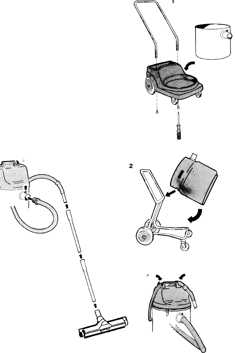
1. UZ 877- The ends of the handle are
inserted into the holes in the base and
secured by two socket head capscrews from
below. The container is than placed on the
base as in figure 1.
UZ 878- The container is placed on the base
as in figure 2.
2. The motor housing is placed on the
container and secured with snapfasteners.
3.The hose is connected to the container via
the inlet stub. Pull up the locking pin and insert
the hose end. Then fit the extension tubes and
nozzle as shown in figure 3.
The hooks on top of the motor housing are for
carrying the hose and the power cable.


