Page -3-
CLARKE TECHNOLOGY 539 Upright Vacuum Operator's Manual
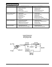
FINAL TEST FOR PRODUCT SAFETY
At the completion of any repairs the product should be
electrically tested for running and electric strength as
follows:
Electric Strength
1. Set hi-pot test meter to 1500 volts.
2. Product switch to ON-position.
3. Touch one probe of tester to one blade of power
cord plug and touch other probe to handle tube.
There should be no breakdown.
Running
Run the machine with the height adjustment knob on
high and check:
1. There should be no abnormal noise or vibration.
2. The carbon brushes spark should be small and
uniform.
3. The current should not exceed 9.0 amps.
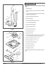
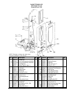
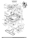
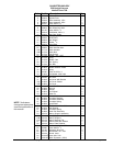
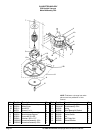
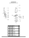
NOTE: The letters with the item no., references,
identify item number on internal (I), external (E) or
motor (M) illustrations.
REPLACEMENT PROCEDURES
1. To Remove Bag (30-E).
Release Spring (36-E) from handle, turn knob on
bag coupling ccw (25-E), slide coupling off unit.
2. To Remove Handle Tube (7-E, 10-E).
a. Disengage line cord from line cord retainer (3E)
pulling cord outward from retainer bottom.
b. Remove bolt and nut (8E and 9E) on handle
socket (24-I) and pull tube out.
3. To Replace The Belt (39-I)
a. Place upright on hood so wheels face upward.
Make sure to place on protected surface not to
damage hood.
b. Remove retaining bar (58-I) by pressing down
on right side (longest), remove brush roll cover
(57-I) and fan cover (38-I).
c. Stretch and twist belt over motor pulley (15-M)
to pull it out. (If not broken).
d. Remove complete brush roll (52-I) with bearing
supports (54-I) pulling it out near the bearings.
e. Place new belt on roll, replace roll on chassis
making sure the mark "top" on bearings
support faces towards the brush roll cover and
reassemble.
4. To Replace the Brush Roll (52-I) or Bearing
Supports (54-I).
a. Follow steps indicated on point 3a and 3b.
b. Remove bearing support (54-I) pulling them
away from brush roll (old or new).
c. Place bearing supports on new brush roll, place
belt over roll and replace it on chassis following
steps 3e.
5. To Replace Rear Wheels (16-I).
a. Remove hood as in step 7.
b. Pull out retainer pin (19-I) from axle, and slide
wheels outward.
c. Replace the new wheel and axle, and insert the
pin.
d. Replace hood.
6. To Replace Front Wheels (42-E).
a. Remove hood as in step 7.
b. Remove screws (44-I) from front axle supports
(45-I) and take out axle assembly.
c. Remove cotter pin (43-E) and flat washer (59-I)
and pull out wheel.
d. Replace the new front wheel, washer and cotter
pin.
e. Replace axle assembly on chassis making
sure springs (51 and 47-I) are in place.
f. Replace hood.
7. To Remove the Hood (17-E).
a. Remove bag and handle tube as in steps 1 and
2.
b. Depress handle release pedal (31-I) and rotate
socket (24-I) to horizontal position.
c. Remove screw from height adjustment knob
(11-E) and pull out knob (12-E).
d. Place upright on hood so wheels face upward,
make sure to place on protected surface not to
damage hood.
e. Remove springs (18-E) from "V" tabs on
chassis, turn upright holding hood and separate
hood from chassis.
8. To Replace Motor (3-I).
a. Remove belt as in steps 3a to 3c.
b. Remove hood as in step 7.
c. Release air ducts (1-I and 15-I) applying
pressure on both sides and slide out.
d. Remove the four motor base screws (4-I)
disconnect switch leads and pull out motor.
9. To Replace Height Adjustment Cam (13-I).
a. Remove hood as in step 7.
b. Slide cam assembly out.
c. Replace new cam and reassemble.
10. To Replace Handle Release Pedal (31-I).
a. Remove hood as in step 7.
b. Remove spring (32-I) from chassis.
c. Pull pedal towards spring slide and remove.


