


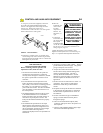
INSTALLATION OF A STANDARD WALL
PUSH BUTTON
If desired, a standard wall push button may be installed
and connected to your operator. A standard wall push
button is not included in your hardware package, it can
be purchased from your professional installing dealer or
a door bell button [without light] can be substituted.
The operating parameters for the standard wall push
button are outlined on a page that follows to see if that
mode of operation is right for you. The Super Station is
included with this operator and the manufacturer rec-
ommends its installation as the Super Station will pro-
vide full control over the garage door at all times.
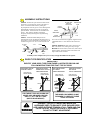
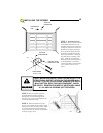
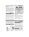
STEP 1: After determining a suitable location,
usually near the access door and
at least 5 feet above
the floor to prevent use by children, use the standard
wall push button as a guide to mark the mounting holes.
Drill holes for drywall anchors or screws. NOTE: Do
not mount directly to masonry walls. Use backer board.
STEP 2: A length of 2-conductor, #22 gauge wire (or
heavier) is required to connect the standard wall push
button to the garage door operator. Strip approximately
2” of the wire jacket from one end and 1/2” of
insulation from each wire. Carefully connect one wire
to each of the two terminals. Carefully tuck the loose
wires into the case and mount the unit using appropriate
screws.
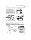
STEP 3: Run the wire from the standard wall
pushbutton to the operator, supporting it at 18” intervals
with suitable staples. Leave a sufficient length to make
the necessary connections to the operator terminal strip.
WARNING: SOME LOCAL BUILDING CODES
DO NOT ALLOW SURFACE WIRING. BE SAFE
AND CHECK WITH YOUR LOCAL BUILDING
INSPECTOR FIRST.
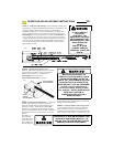
STEP 4: Ensure power is OFF to the operator or
disconnect the power from the operator. Strip
approximately 4” of jacket from the end of the wire and
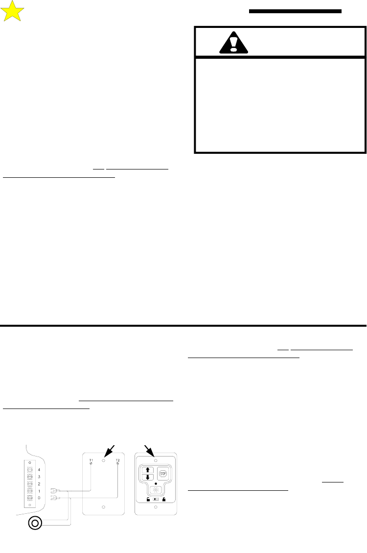
1/2” insulation from each wire. Connect to terminals 0
and 1 as shown in the illustration below. Support the
wire near the operator with wire ties.
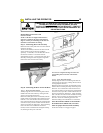
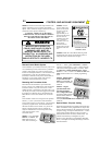
Step 5: Install the Control Button Warning Label
supplied with your opener near the standard wall push
button (see illustration next page).
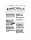
WARNING
A CHILD OPERATING THE DOOR
CONTROLS RISKS INJURY — OR DEATH
— TO HIMSELF (HERSELF) AND OTHERS.
DO NOT ALLOW CHILDREN TO OPERATE
ANY DOOR CONTROLS.
MOUNT THE PUSHBUTTON AT LEAST 5
FEET FROM THE FLOOR, OUT OF REACH
OF CHILDREN.
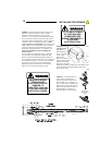
INSTALLATION OF THE SUPER STATION
The Super Station (Deluxe Wall Pushbutton Station) is
a 7 function station designed to work with and
maximize the functionality of your garage door opener.
Connection to any other opener may damage the opener
and/or the Super Station. Only connect one Super
Station to each opener. Do not connect more than one
Super Station to an Opener.
STEP 1:
After determining a suitable location,
usually near the access door and
at least 5 feet above
the floor to prevent use by children, use the Super
Station as a guide to mark the mounting holes. Drill
holes for drywall anchors or screws. NOTE: Do not
mount directly to masonry walls. Use backer board.
The Super Station is also designed to be mounted
directly to a standard single electrical box.
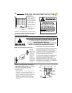
STEP 2: A length of 2-conductor, #22 gauge wire (or
heavier) is required to connect the Super Station to the
garage door opener. Strip approximately 6” of the wire
jacket from one end and 1/2” of insulation from each
wire. Carefully connect one wire to each of the two
terminals indicated, noting which color is connected to
which terminal. Tighten screws, being careful that no
wires are allowed to touch any other terminal or any
other conductive part of the circuit board. Do not
overtighten the terminal screws.
STEP 3: Push the wire jacket into one of the two
notches provided at the ends of the housing, allowing a
maximum of 1/8” inch of the jacket inside the case (too
much will make mounting difficult). Carefully tuck the
loose wires into the case and mount the unit using the
screws provided.
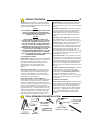
BACK
STANDARD WALL
PUSH BUTTON
108387
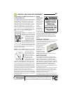
SUPER STATION
DELUXE WALL PUSH
BUTTON
MOUNTING
HOLES
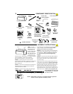
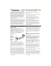
CONTROL AND AUXILIARY EQUIPMENT
10