


13
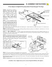
D: CONTROL AND AUXILIARY EQUIIPMENT
SAFE FINISH™ PHOTOSYSTEM INSTALLATION
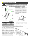
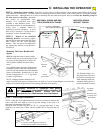
Identify which side of the garage door opening (if any) the sun is “likely” to shine
into. As sunlight may cause undesirable operation, mount the sending unit (black
button below the window) on the side of the door opening exposed most to the sun.
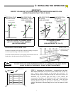
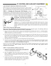
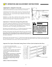
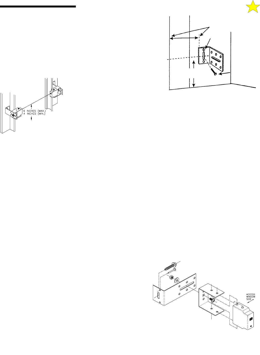
STEP 1: Mounting the Photosystem Wall Brackets Select a
mounting position 5 inches above the floor to the center line wall bracket. The
sending and receiving units should be mounted inside the door opening to minimize
any interference by the sun. However, the sensors should be mounted as close to
the door track or inside edge of the door as possible to offer maximum entrapment
protection. The brackets may be temporarily
mounted to the wall (or jamb) with the 1” flathead
nail provided. Leave this nail in place after
installation of the lag screw below to prevent
accidental rotation of the bracket NOTE: It is very important that the wall brackets be mounted at
exactly the same height so they will be aligned.
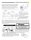
Using the 1/4” x 1-1/2” lag screw provided, attach the wall bracket securely to the wall. In some
installations it may be necessary to attach wooden spacers to the wall to achieve the required
clearance. Expansion bolts (not supplied) may be required to attach brackets to walls constructed of
materials other than wood or gypsum. Repeat for the wall bracket on the other side of the door
opening.
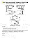
STEP 2: Wire Connect the Photosystem
Refer to page 20 for wiring diagrams of the Safe Finish™ Photosystem and garage door opener. The following outlines the
“PHOTOCELL SERIES CONNECTION (RECEIVER FIRST)” wiring diagram.
A. Run a wire pair (not supplied) around the garage door jamb between the transmitter and receiver "L" mounting brackets.
NOTE: Leave about 12” of extra wire at each end. Use a minimum 22 gauge solid "trace" wire (one wire in set should be
marked to identify it at each end) for interconnect.
B. Run a wire pair (20 or 22 gage solid wire) from the receiver position (unit with "LED" light in the front, may be either side of
the door) back to the rear bulkhead of the garage door opener. NOTE: Leave about 12” of extra wire at the receiver end and
about 24” of extra wire at the opener end. Use a minimum 22 gauge solid "trace" wire (one wire in set should be marked to
identify it at each end) for interconnect.
C. Strip approximately 5/16” from each wire end at the photosystem units and at the opener.
D. Using two (2) wire nuts (supplied), connect the wire ends at the Safe Finish™ Photosystem transmitter to the pigtail wire ends
coming out of the transmitter unit.
Observe polarity, connect the trace wire ends (with black stripe) together and the
unmarked wire ends together. See wiring diagrams on page 20 .
Using two (2) wire nuts (supplied), connect the wire ends at the SAFE FINISH™ Photosystem receiver to the pigtail wire ends
coming out of the receiver unit.
Observe polarity, connect the trace wire ends (with black stripe) together and the
unmarked wire ends together.
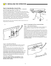
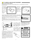
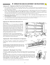
STEP 3: Final Installation of Photosystem Units
A. Attach the"U" brackets to the "L" brackets with a 1/4-20 carriage bolt,
washer and hex nut (provided). Insert the bolt from the inside of the
"U" bracket and hand tighten only at this time.
B. Place the transmitter and receiver units into their respective "U"
brackets. NOTE: It is easier to slip the photosystem units in from the
side of the bracket than forcing them in from the front of the bracket.
See Illustration, at right.
C. Connect the interconnect wire pair to the garage door opener terminals.
Connect the trace wire (with black stripe) to the operator
terminal marked “4” and the solid color wire to the operator
terminal marked “5”. See Wiring Diagrams on page 20 .
104382
104383
1/4” x 1-1/2”
Lag Screw
5 Inches
Above the Floor
#8 Hex
Head
Screw
12 Inches From Door Opening
110052-1