B. Standard hook-up to three terminal operators:
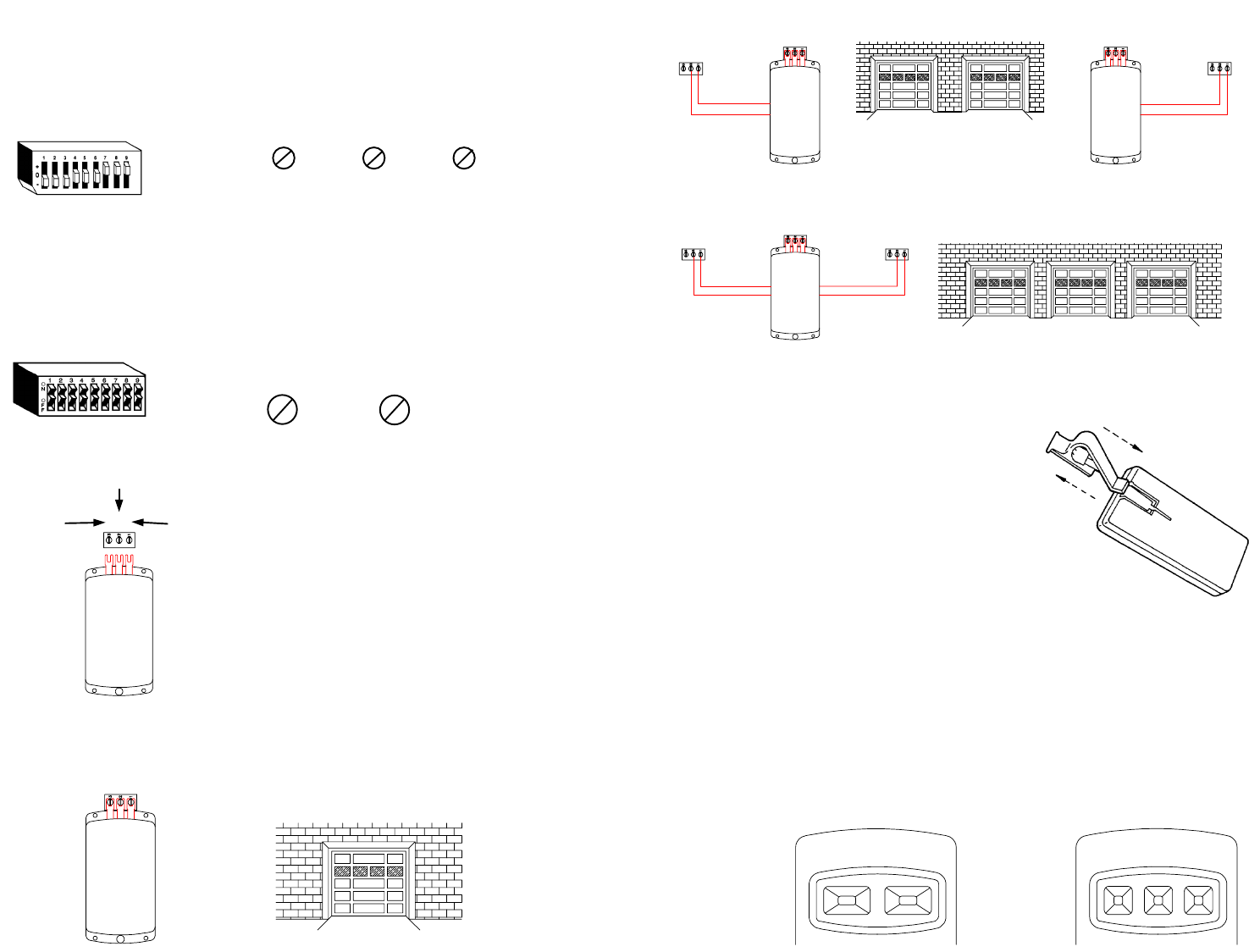
For direct connection loosen the three screws
on the operator and slide the brass terminals
under these screws. See Fig. 4. Replace the
pushbutton wiring and tighten the screws. Be
certain the antenna wire is hanging down
vertically and the receiver terminal numbers
printed on the receiver case match the
numbers on the operator terminal strip.
IMPORTANT: THE EXACT SAME CODE MUST BE
SET ON BOTH THE TRANSMITTER AND RECEIVER.
IF JUST ONE SWITCH IS MISMATCHED THE
CONTROLS WILL NOT FUNCTION.
MODEL 9921 AND 8822: The coding switch in these models consists of eight or nine
small switches each of which can be placed in two different positions, On or Off. See
Fig. 3. Using a small screwdriver, set the coding switches in both the transmitter and
receiver identically. (Your private code).
DO NOT SET ALL SWITCHEs IN THE SAME POSITION.
EXAMPLE:
Models 9931, 8832, 8833: The coding switch in these models consist of eight or nine
small switches, each of which can be placed in any of three different positions. (+, 0, -). See
Fig. 2. Using a small screwdriver, set both the transmitter and receiver coding switches
identically. (Your private code setting).
DO NOT SET ALL THE SWITCHES IN THE SAME POSITION.
EXAMPLE:
STEP 2: INSTALL YOUR RECEIVER
A. The receiver was designed to be installed in a
variety of ways depending on the type of
operator and the application. If standard
hook-up is not desirable or possible,
accessories such as three wire adapter sets
and transformer adapter kits must be used.
NOT ALL + or 0 or -
NOT ALL ON or OFF
(1)
3 2 1
FIGURE 3
C. Models 9921 or 9931
Single Door Garage
RELAY
24 VOLTS
COMMON
RADIO
POWER
3 2 1
FIGURE 4
FIGURE 2
104386
STEP 3: INSTALL YOUR TRANSMITTER
A. The transmitter can be either hand held or
mounted on the sun visor with the enclosed visor
clip. If sun visor mounting is desired attach the
visor clip as shown. (See Fig. 5)
If removal of the visor clip is necessary, place finger in
loop at top of visor clip, and thumb on top edge of
transmitter. Push down with thumb and pull up with
index finger. Clip should release and pull out easily.
B. If the operating distance drastically decreases, remove the battery access door See Fig.
1A, and replace the battery with a NEDA 1604, nine volt battery.
C. Models 9921 and 9931: To activate your garage Door or Gate, simply depress your
transmitter button until the door or gate starts to move.
D. Models 8822, 8832 and 8833: To activate the desired Garage Door or Gate control,
push either button (1) one, (2) two or (3) three, depending on which you desire to open
or close. Channel one (1) is the left button. Channel (2) is the center button. Channel
three (3) is the right button.
D. Model 8832 - Double Door Garage
MODELS
8822 & 8832
MODEL
8833
(1)
(3)
(2)
3 2 1
3 2 1
3 2 1
3 2 1
3 2 1
3 2 1
3 2 1
E. Model 8833 - Three Door Garage
(2) (1)
FIGURE 5
104388


