


506725-01Page 26 of 48 Issue 1109
Do Not use copper tubing or existing copper condensate
lines for drain line.
CAUTION
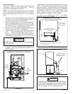
Condensate Piping
This unit is designed for either right or left side exit of
condensate piping in downflow applications. Refer to
Figure 38 for condensate trap locations.
NOTE: If necessary the condensate trap may be installed
up to 5” away using PVC pipe from the furnace. Piping from
furnace must slope down a minimum of 1/4” per ft. toward
trap.
1. Determine which side condensate piping will exit the
unit, location of trap, field-provided fittings and length of
PVC pipe required to reach available drain.
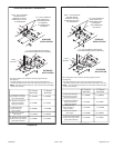
2. Remove plug (Figure 38) from the cold end header box
at the appropriate location on the side of the unit. Install
field-provided 1/2 NPT male fitting into cold end header
box. Use Teflon tape or appropriate pipe dope.
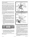
3. Install the cap over the clean out opening at the base of
the trap. Secure with clamp. See Figure 41.
4. Install drain trap using appropriate PVC fittings, glue all
joints. Glue the provided drain trap as shown in
Figure 41. Route the condensate line to an open drain.
Condensate line must maintain a 1/4” downward slope
from the furnace to the drain.
5. If unit will be started immediately upon completion of
installation, prime trap per procedure outlined in Unit
Start-Up section.
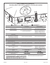
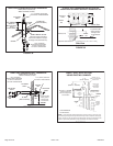
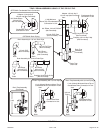
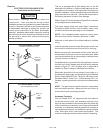
FIGURE 39
CONDENSATE TRAP LOCATION
(shown with right side exit of condensation)
5’ max.
to drain
Field Provided Vent
min. 1" Above
Condensate Drain
1" min.
Trap can be installed a
maximum of 5 ft. from furnace.
(*PVC Only)
*Piping from furnace must slope down a minimum of
1/4" per ft. toward trap.
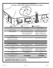
FIGURE 40
UNIT WITH EVAPORATOR COIL
Drain
Condensate trap and
evaporator coil must drain
separately as shown.
Field−Provided Vent
A separate drain line must be run to the drain from the
condensate trap to ensure proper drainage and pressure
switch operation. DO NOT connect the condensate trap
drain into the drain line from the evaporator coil.
CAUTION
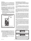
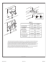
FIGURE 38
CONDENSATE TRAP AND PLUG LOCATIONS
Trap
(same on
right side)
Plug
(same on left
side)
1−1/2 in.
Condensate line must slope downward away from the trap
to drain. If drain level is above condensate trap, condensate
pump must be used. Condensate drain line should be routed
within the conditioned space to avoid freezing of condensate
and blockage of drain line. If this is not possible, a heat
cable kit may be used on the condensate trap and line.
Heating cable kit is available in various lengths:
6 ft. (1.8 m) - kit no. 26K68; 24 ft. (7.3 m) - kit no. 26K69;
and 50 ft. (15.2 m) - kit no. 26K70.