


1. Follow the recommended instructions for the proper
method of wiring your ceiling fan. If you do not know
enough about electrical wiring, have your fan installed by
a licensed electrician.
2. All wiring must satisfy National and Local electrical codes.
The ceiling fan must be grounded as a precaution against
possible electrical shock.
3. The electrical outlet box and joist must be securely mounted
and capable of reliably supporting at least 50 pounds.
4. WARNING: To reduce the risk of fire, electrical shock
and/or personal injury:
a) Be sure electricity is turned off at the main fuse box
before wiring, cleaning or servicing.
b) Fan should not be mounted in areas where it might
come in direct contact with water.
1. Be careful of the fan and moving blades when cleaning,
painting or working near fan.
2. Do not put anything into the blades while they are turning.
3. Do not bend the blade brackets when installing the brackets,
balancing the blades or cleaning the fan.
4. WARNING: The fan must be hung with at least 7 feet of
clearance from floor to blades.
RULES FOR SAFE INSTALLATION
RULES FOR SAFE OPERATION
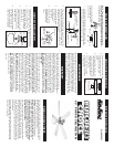
1. Attach the hanger bracket to the electrical box capable of
reliably supporting at least 50 pounds. Insert the screws
through the slotted holes in the bracket and attach to the
electrical box. Tighten both screws to the electrical box.
(Figure 1)
NOTE: If bracket and/or electrical box are not securely
attached, the fan could wobble.
INSTALLATION INSTRUCTIONS
WARNING: Failure to completely install the cotter pin or
tighten the set screw could result in the fan loosening and
possibly falling.
NOTE: Check to see that all connections are tight, including
the ground and that no bare wire is visible at the wire nuts,
except for the ground wire.
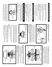
8. Raise canopy up to mounting bracket and fit screws into
slots on canopy and rotate to the left to lock into place.
Tighten both screws.
(Figure 5)
NOTE: Make sure that the electrical wires are completely
inside the electrical box and not pinched between the ceiling
canopy and the ceiling.
Figure 4
White Fan
(Neutral)
Black Fan
(Hot)
Green Jumper
Wire
Supply Ground
Green or Bare
Black Supply
(Hot)
White Supply
(Neutral)
Figure 1
Screw
Electrical Box
Mounting
Bracket
3. Carefully lift the fan and seat the pipe flange and ball
assembly on the hanger bracket that was just attached to
the electrical box. Be sure the notch on the side of the ball
is lined up with tab on the hanger bracket.
(Figure 3)
WARNING: Failure to seat tab on bracket into notch on ball
could cause damage to electrical wires and cause fan to fall.
NOTE: Do not pinch wires between the ball and pipe flange
assembly and hanger bracket.
Figure 2
Pipe Flange
Yoke Cross Pin
Cotter Pin
Canopy
Set Screw
Cotter Pin
4. Make sure the electrical box is properly secured. If romex
cable (plastic sheathed) was used to wire the electrical
box, the presence of a third wire connected to the electrical
box indicates that the box is grounded. This ground wire
may be bare wire (no insulating jacket), or a green insulated
wire. The two supply wires will be white and black insulated
wires.
5. If the wiring to the electrical box is enclosed in electrical
conduit pipe, the ground wire may not be present. The
conduit itself could serve as the ground.
GROUNDING:
6. Romex (plastic sheathed) Cable: If romex cable was used
to wire the electric box, connect the green ground wire
attached to the hanger ball and the green ground wire in
the Romex cable using a 72B listed wire nut.
6a. Conduit Pipe: If the wiring to the electrical box is enclosed
in electrical conduit pipe, connect the ground wire to the
ground screw in the electrical box.
Figure 3
NOTE: Ceiling canopy
supply wires and fan wires
omitted from figure for
clarity
Electrical Box
Pipe Flange
Assembly
7. Electrical Supply: Connect the fan motor white wire to the
supply white (Neutral) wire using a listed wire nut. Connect
the fan motor black wire and blue wire to the supply black
(hot) wire using a listed wire nut. Your fan is now wired
to be turned on and off from the fan (pull chain) switch.
(Figure 2)
With wire nuts turned upward, place green and
white connections to one side of box and blue and black
connections towards the other side and push carefully up
into outlet box.
2. Install motor leads through the canopy then through the
hole in the center of the pipe flange. Insert downrod into
downrod yoke. Make sure to align hole in downrod with
hole in downrod yoke. Lift canopy and install yoke cross
pin through yoke and downrod. Insert cotter pin into cross
pin until it snaps into place. Using a phillips head
screwdriver firmly tighten set screws in yoke.
(Figure 2)
Figure 5
Scre
Canopy
Mounting
Bracket