


www.airkinglimited.com
984856M1 Rev. A 9-06
2 of 4
INSTALLATION INSTRUCTIONS
CAUTION:
MAKE SURE POWER IS SWITCHED OFF AT
SERVICE PANEL BEFORE STARTING INSTALLATION.
SECTION 1
Installation Requirements
1. Electrical Requirements: This unit requires a grounded
electrical supply line of 120 volts AC, 60 Hz, 15 amp circuit.
WARNING: TO REDUCE THE RISK OF FIRE, ELECTRIC
SHOCK, OR PERSONAL INJURY, PROPERLY INSTALL TO AN
OUTLET BOX MARKED “ACCEPTABLE FOR FAN SUPPORT”. USE
SCREWS PROVIDED WITH OUTLET BOX. MOST OUTLET BOXES
COMMONLY USED FOR THE SUPPORT OF LIGHTING FIXTURES
ARE NOT ACCEPTABLE FOR FAN SUPPORT AND MAY NEED TO
BE REPLACED. CONSULT A QUALIFIED ELECTRICIAN IF IN DOUBT.
2. Electrical Box: This unit will fit any of the following electrical
boxes: 4" octagon box, 3" octagon box, 1/2" deep ceiling pan,
or a plaster ring with 3-1/2" mounting hole centers mounted
on one of the above listed boxes. This fan will also install on
a “Wiremold” No. 5738 fixture box. The electrical box must
be securely anchored and capable of withstanding a load of
at least 35 pounds.
CAUTION: IF ONE OF THE ABOVE ELECTRICAL BOXES IS
NOT PRESENT FOR PROPER INSTALLATION, CONTACT A
LICENSED ELECTRICIAN.
SECTION 2
Preparing the Ceiling Fan
1. Unpack fan from the carton and confirm that all pieces are
present. The following should be present:
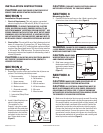
2. Install J-Hook Bracket to an
electrical box marked
“Acceptable For Fan
Support” using the screws
provided with the outlet box.
Insert the screws through the
slotted holes in the bracket
and attach to the electrical
box. Tighten both screws
(Figure 1).
Figure 1
Screw
Electrical Box
J-Hook
Bracket
CAUTION: IF BRACKET AND/OR ELECTRICAL BOX ARE
NOT SECURELY ATTACHED, THE FAN COULD WOBBLE.
SECTION 3
Mounting the Fan
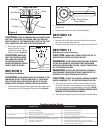
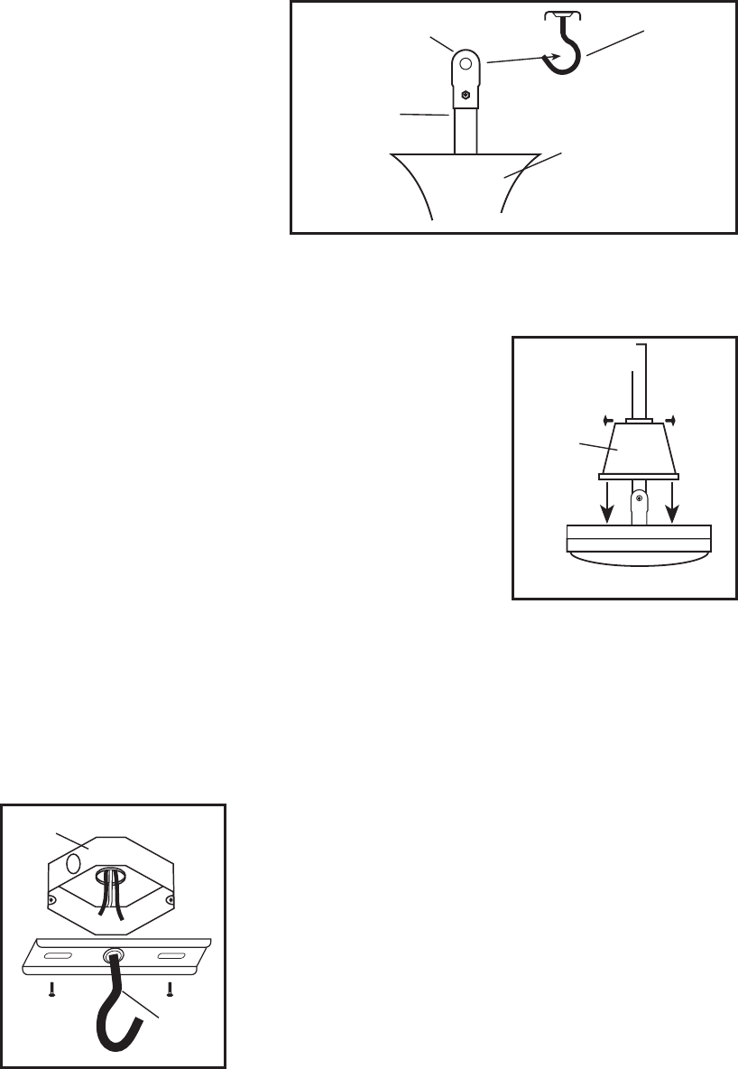
2. Carefully lift the fan and hang on the J-Hook, ensuring that
all wires are clear of the rubber roller (Figure 2).
WARNING: FAILURE TO SEAT DOWNROD ASSEMBLY ON
J-HOOK BRACKET COULD CAUSE DAMAGE TO ELECTRICAL
WIRES AND CAUSE FAN TO FALL.
CAUTION: DO NOT PINCH
WIRES BETWEEN THE J-HOOK
AND DOWNROD ASSEMBLY.
2. Slide lower canopy down
the downrod until it is snug
against the motor housing.
Tighten both set screws
(Figure 3).
SECTION 4
Wiring
CAUTION: MAKE SURE POWER IS SWITCHED OFF AT
SERVICE PANEL BEFORE STARTING INSTALLATION.
CAUTION: ALL ELECTRICAL CONNECTIONS MUST BE
MADE IN ACCORDANCE WITH LOCAL CODES, ORDINANCES,
OR NATIONAL ELECTRICAL CODE. IF YOU ARE UNFAMILIAR
WITH METHODS OF INSTALLING ELECTRICAL WIRING, SECURE
THE SERVICES OF A QUALIFIED ELECTRICIAN.
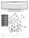
1. Make sure the electrical box is properly secured. Run wiring
from an approved wall switch carrying the appropriate rating.
One neutral (white), one ground (green or bare copper), and
one hot (black lead connected to the switch).Connect the
white wire from the fan to the white wire from the supply.
Connect the black wire from the fan to the black (hot) wire
from the wall switch. Connect the green or bare copper
ground wire from the house to the green wire from the fan.
Use approved methods for all connections and carefully push
wires up into the outlet box (Figure 4).
Figure 2
J-Hook Bracket
Downrod
Rubber Roller
Upper Canopy
NOTE: Wires omitted from figure for clarity
NOTE: Wires omitted
from figure for clarity
Figure 3
Screw
Lower
Canopy
1 - Motor assembly 1 - Package containing:
1 - Lower canopy 4 - Flat washers
1 - Upper canopy 2 - 8/32" screws
6 - Blade lock washers 2 - #8 lock washers
6 - Blade screws 2 - #10 lock washers
1 - Downrod assembly 3 - Wire nuts
1 - J-hook bracket 2 - Wood screws
1 - Instruction/Safety Sheet
3 - Blades