


Rev. C 9/07
5084413
2
PRODUCT USAGE
To complete this Air King
®
High Velocity Head Assembly use any of the following Air King
®
products:
Model # 9100PB - Pedestal and Base Kit
Model # 9100WC - Wall Mount Kit
Model # 9100CM - Ceiling Mount Kit
Model # 9100WB - Wheel Kit
Model # 9100I - I-Beam Kit
See Related Product For Assembly Attachment Instructions.
MAINTENANCE
WARNING: ALWAYS UNPLUG THE CORD BEFORE MOVING OR SERVICING.
WARNING: DO NOT IMMERSE FAN IN WATER!
CLEANING: Use a soft cloth and mild soap solution such as liquid dish washing detergent. Dry all parts completely before reconnecting to
power supply.
CAUTION: Do not use gasoline, benzine, thinner, harsh cleaners, etc. as they will damage the Fan. NEVER use
ALCOHOL OR SOLVENTS.
SERVICING: All other servicing, with the exception of general user maintenance, should be performed by an authorized service representative.
Call 1-800-233-0268, Monday through Friday, between the hours of 8:00 a.m.and 5:00 p.m. Eastern for the location of your nearest service
center.
LUBRICATION: Precision bearings are sealed at the factory for life and do not require further lubrication.
STORAGE: Store the Fan, with these instructions, in a clean and dry place.
CAUTION: TO REDUCE THE RISK OF FIRE, ELECTRICAL SHOCK OR PERSONAL INJURY, ONLY
USE WITH ONE OF THE FOLLOWING AIR KING MODELS; 9100PB, 9100WC, 9100CM, 9100WB,
9100I.
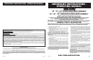
GRILL AND BLADE ASSEMBLY (Figures 1 and 2)
NOTE: The assembly of the blade and grill are identical, regardless if the Fan has an oscillating motor or a non-oscil-
lating motor. One of each is shown in the illustrations below.
1. Install the Rear Grill onto the Motor, lining up the six holes in the grill with the six threaded holes in the Motor. Install (6) 10-32 X 5/16"
Hex Screws through the Rear Grill into the Motor. Securely tighten all (6) screws. (Figure 1)
2. Push the Fan Blade onto the Motor Shaft, centering the Hub facing away from the motor, until it stops against the shaft. (Inset A) Align
Square Head Bolt with at of the Motor Shaft. TIGHTEN VERY SECURELY WITH AN ADJUSTABLE WRENCH. Failure to securely tighten
the Bolt could result in damage to the Fan and/or personal injury.
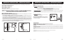
3. Hold the Front Grill so that the name, in the center, is right side up and straight across. Starting at the top: Fasten Front Grill to Rear Grill
by sliding the hooked wires on the Front Grill over the outermost ring on the Rear Grill. (Figure 2 / Detail A) The bottom most hooks will
require the use of a athead screwdriver to complete assembly. Stand behind the Fan. Slip the at of the screwdriver between the Front
and Rear Grills, next to one of the unfastened hooks. (Figure 2 / Detail B) Pull screwdriver handle upwards towards the Rear Grill. Slip the
Front Grill hook over the Rear Grill outer ring with a push. Repeat procedure with remaining hooks.
CAUTION: DO NOT BEND WIRES ON THE FRONT OR THE REAR GRILLS.
OPERATING INSTRUCTIONS
1. TO OPERATE: Plug cord into a grounded 120V, 60 Hz outlet. Select desired operating speed with pull cord on the rear of the motor:
First pull: High Second pull: Medium
Third pull: Low Fourth pull: OFF
NOTE: THIS FAN IS VERY HEAVY.
Failure to securely hold onto head assembly while adjusting head angle
could result in personal injury.
2. TO ADJUST HEAD ANGLE: While holding head rmly, loosen knob under motor (turn counterclockwise). Tilt head to desired position
FIRMLY retighten knob under motor.
NOTE: Motor Head Adjustment Knob and the On/Off Pull Cord have the same location on oscillating or non-oscillating models.
Figure 1
Inset A
Oscillating Motor Shown
Detail B
Bottom Hooks
Detail A
Top Hooks
Non-Oscillating Motor Shown
Figure 2
NOTE: The Grill and Blade should be installed AFTER the Motor
Head Assembly has been properly mounted.
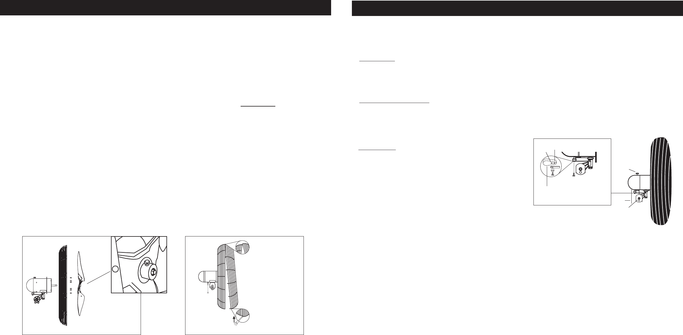
FOR OSCILLATING MODELS:
3. OSCILLATION: Push down oscillation knob on motor housing to
make fan head move from side to side.
NOTE FOR OSCILLATING MODELS: FAN IS SHIPPED WITH
90º OSCILLATION ANGLE. FOR 45º OSCILLATION ANGLE,
CONNECT THE OSCILLATION LINK TO THE INNERMOST HOLE
IN THE CAM GEAR. (Inset A)
1.
2.
3.
(Inset A)
Cam Gear
90˚
45˚
Rev. C 9/07
5084413
3
IMPORTANT INSTRUCTIONS - OPERATING MANUAL
IMPORTANT INSTRUCTIONS - OPERATING MANUAL