


MODEL 9125/9135
OPERATING INSTRUCTIONS
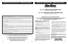
1.)TO OPERATE: Plug cord into a grounded 120V, 60 Hz outlet. Select
desired operating speed with pull cord on the rear of the motor:
First pull: High Second pull: Medium
Third pull: Low Fourth pull: OFF
NOTE: This fan is very heavy. Failure to securely hold onto head
assembly while adjusting head height or head angle could result in
personal injury.
2.)
TO ADJUST HEAD ANGLE: While holding head firmly, loosen
knob under motor (turn counterclockwise). Tilt head to desired
position FIRMLY retighten knob under motor.
3.)
TO ADJUST HEAD HEIGHT: While holding upper column firmly,
loosen set screw on column collar (turn counterclockwise). Raise or
lower head to desired position. FIRMLY retighten set screw.
NOTE: Motor Head Adjustment Knob, On/Off Pull Cord and Set
Screw Placement have the same location on oscillating or non-
oscialling models.
2 5084415New 3/04 3 5084415New 3/04
TOOLS REQUIRED FOR ASSEMBLY
• 2 Adjustable Wrenches (min 3/4” open)
• Flathead Screwdriver
• 3/16 Allen Wrench (supplied in parts bag)
NOTE: BECAUSE OF THE SIZE AND WEIGHT OF THIS FAN, ASSEMBLY
MAY REQUIRE TWO PEOPLE.
NOTE: ALL HARDWARE REFERRED TO IN THE INSTRUCTIONS MAY
BE FOUND IN THE SUPPLIED PARTS BAGS.
BASE ASSEMBLY
(Figure 1)
1. Place Base on floor.
2. Fit Mounting Flange through large hole in center of Base.
3. Insert (4) 3/8-16 X 1” Carriage Bolts through Mounting Flange
and Base.
4. Tilt Base and secure one Carriage Bolt at a time by first putting
on a 3/8” Split Lockwasher and then a 3/8-16 Hex Nut. DO
NOT FULLY TIGHTEN AT THIS TIME. Repeat above procedure
with remaining Bolts.
5.
GO BACK AND FULLY TIGHTEN each Hex Nut so that the
Flange is securely assembled to the Base.
6. Thread the 3/8-16 X 3/4” Set Screw into the Mounting Flange.
Figure 1
Mounting Flange
Carraige Bolts (4)
Set Screw
Base
Hex Nut (4)
Split Lockwasher (4)
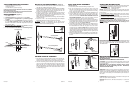
MOTOR & COLUMN ASSEMBLY
(Figure 2)
1. Remove motor from foam, place on a stable level surface on its
side with the oscillation shaft facing upward.
2. Slide flat section on Upper Tube of Column Assembly inside Motor
Mounting Bracket Slot. Align the 1/2" diameter Hole in the flat
section on the Upper Tube of Column Assembly with the 1/2"
diameter Hole in the Motor Mounting Bracket.
3. Insert the 1/2" diameter x 1" long Hex Bolt (3/4" head) through
the Motor Bracket, and the Upper Tube Assembly. Place 1/2" di-
ameter Split Lockwasher then 1/2" diameter Nut (3/4" hex) and
tighten fully with 2 Adjustable Wrenches.
NOTE: Secure these parts before continuing to the Column/Base
Assembly section.
4. Insert one 1/4-20 x 1 3/8" Carriage Bolt through the Arc-Shaped
Slot in Motor Bracket and Hole in Upper Pipe of Column.
To Fasten: Place one 1/4" Flatwasher, one 1/4" Internal Tooth
Lockwasher, a second 1/4" Flat Washer and then tighten the Ad-
justment Knob over the remaining threads.
COLUMN TO BASE ASSEMBLY
1. Rest Column and Head Assembly on floor next to the Base As-
sembly. Tilt Base Assembly up on end. Pick up Lower Pipe of
Column and insert bottom of Pipe into the Mounting Flange.
2. Tilt entire Assembly (base and head) upright. Confirm that the
column is fully seated in Mounting Flange. Insert and securely
tighten the 3/8"-16 x 3/4" Allen Set Screw in Mounting Flange
with the Allen Wrench (supplied in parts bag). Make sure Screw
is fully tightened and there is NO looseness between Column
and Mounting Flange.
GRILL AND BLADE ASSEMBLY
(Figures 3 and 4)
1. Loosen knob, tilt fan head back halfway, retighten knob.
2. Put rear grill onto motor, Lining up the six holes in the grill
with the six threaded holes in the mounting flange. Install six
10-32 x 5/16 hex bolts through the grill into the mounting
flange. Securely tighten all bolts.
3. Loosen knob and return head to a vertical postion. Retighten knob.
4. Push fan blade onto motor shaft, center hub facing away from
motor, until it stops against shaft. Align bolt head set screw with
flat of the motor shaft. TIGHTEN VERY SECURELY WITH AN
ADJUSTABLE WRENCH. Failure to securely tighten set screw
could result in damage to the fan and/or personal injury.
5. Hold the front grill so that the name, in the center, is right side up
and straight across. Starting at the top: Fasten front grill to rear
grill by sliding the hooked wires on the front grill over the Outer-
most Ring on the rear grill.
(Figure 4-Detail A)
6. The bottom most Hooks will require the use of a flathead screw-
driver to complete assembly. Stand behind Fan. Slip the flat of
the blade between the front and rear grills, next to one of the
unfastened hooks.
(Figure 4-Detail B)
Pull screwdriver handle
upwards towards the rear grill. Slip the front grill hook over the
rear grill outer ring with a push. Repeat procedure with remaining
Hooks. Caution: Be careful not to bend any wires on grills or pinch
your hands during assembly.
7. Attach pull cord to pull chain. Fan assembly is now complete. Re-
fer to sections below for correct operating instructions and main-
tenance.
NOTE FOR OSCILLATING MODELS: FAN IS SHIPPED WITH
90º OSCILLATION ANGLE, FOR 45º OSCILLATION ANGLE, CON-
NECT THE OSCILLATION LINK TO THE INNERMOST HOLE IN
THE CAM GEAR.
Oscillating Model
Detail A
Top Hooks
Detail B
Bottom Hooks
Figure 4
Figure 3
Figure 3
Figure 4
Detail B
Bottom Hooks
Detail A
Top Hooks
Non-Oscillating Model
MAINTENANCE
WARNING: ALWAYS UNPLUG THE CORD BEFORE MOV-
ING OR SERVICING.
WARNING: DO NOT IMMERSE FAN IN WATER!
CLEANING: Use a soft cloth and mild soap solution such as liquid
dish washing detergent. Dry all parts completely before reconnect-
ing to power supply.
CAUTION: Do not use gasoline, benzine, thinner, harsh
cleaners, etc. as they will damage the Fan. NEVER use
ALCOHOL OR SOLVENTS.
SERVICING: All other servicing, with the exception of general user
maintenance, should be performed by an authorized service repre-
sentative. Call 1-800-233-0268, Monday through Friday, between the
hours of 8:00 a.m.and 5:00 p.m. for the location of your nearest ser-
vice center.
LUBRICATION: Precision bearings are sealed at the factory for life
and do not require further lubrication.
STORAGE: Store the Fan, with these instructions, in a clean and
dry place.
Figure 2
Oscillating Model
Non-Oscillating Model
Front View
Figure 2A
1.
2.
3.
Cam
Gear