


IMPORTANT INSTRUCTIONS - OPERATING MANUAL IMPORTANT INSTRUCTIONS - OPERATING MANUAL
2Rev. A 9/07
5084414
3Rev. A 9/07
5084414
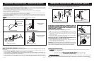
GRILL AND BLADE ASSEMBLY (Figures 5 and 6)
NOTE: The assembly of the blade and grill is identical, regardless if the Fan has an oscillating motor or a non-oscil-
lating motor.
1. Install the Rear Grill onto the Motor, lining up the six holes in the grill with the six threaded holes in the Motor. Install (6) 10-32 X 5/16"
Hex Screws through the Rear Grill into the Motor. Securely tighten all (6) screws. (Figure 5)
2. Push the Fan Blade onto the Motor Shaft, centering the Hub facing away from the motor, until it stops against the shaft (Inset A) . Align
Square Head Bolt with at of the Motor Shaft. TIGHTEN VERY SECURELY WITH AN ADJUSTABLE WRENCH. Failure to securely tighten
the Bolt could result in damage to the Fan and/or personal injury.
3. Hold the Front Grill so that the name, in the center, is right side up and straight across. Starting at the top: Fasten Front Grill to Rear Grill
by sliding the hooked wires on the Front Grill over the outermost ring on the Rear Grill. (Figure 6 / Detail A). The bottom most hooks will
OPERATING INSTRUCTIONS
1. TO OPERATE: Plug cord into a grounded 120V, 60 Hz outlet. Select desired operating speed with pull cord on the rear of the motor:
First pull: High Second pull: Medium
Third pull: Low Fourth pull: OFF
NOTE: THIS FAN IS VERY HEAVY.
Failure to securely hold onto head assembly while adjusting head angle
could result in personal injury.
2. TO ADJUST HEAD ANGLE: While holding head rmly, loosen knob under motor (turn counterclockwise). Tilt head to desired position
FIRMLY retighten knob under motor.
NOTE: Motor Head Adjustment Knob and the On/Off Pull Cord have the same location on oscillating or non-oscillating models.
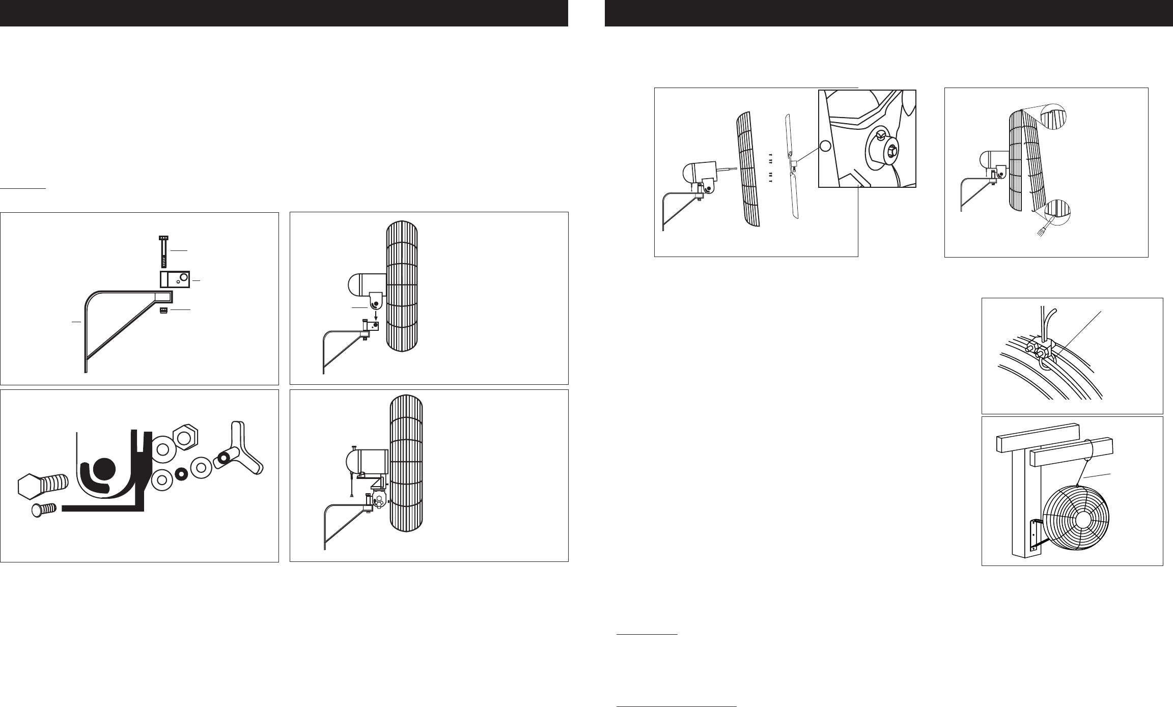
CAUTION: THE SECONDARY SUPPORT CABLE
PROVIDED SHOULD BE USED ANYTIME THE
CIRCULATOR IS MOUNTED OVERHEAD FOR
ADDITIONAL SAFETY.
SECONDARY SUPPORT CABLE (Figures 7 and 8)
1. Loop one end of Cable around the Large Guard Wires of both the Front and Rear
Grills.
2. Attach a Cable Clamp with the "U" on the tail side of the loop leaving a tail
approximately 1 to 2 inches. Tighten Clamp Nuts. Make sure no part of the Cable
interferes with the Blade.
3. Wrap the other end of the Cable around a secure building joist, truss, or other sup-
port near the Fan. Take up all excess slack in the Cable.
CAUTION: USE ONLY THE MOUNTING HARDWARE WHICH
IS RECOMMENDED FOR USE ON THIS FAN.
4. Attach the remaining Cable Clamp as indicated in Step 2. The excess tail should be
trimmed to extend 1 to 2 inches past the Clamp.
5. Check the Assembly to assure the Blade is free of all obstructions.
CAUTION: Use of the secondary support cable does not guarantee
protection against injury of persons, mounting of both the circulator and
cable could fail if subjected to abuse, neglect or improper installation.
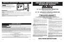
WALL BRACKET INSTALLATION (Figures 1 through 4)
NOTE: Always install the bracket to a minimum of 2" x 4" studding.
1. Insert the 7/16-14 x 3-1/2" Bolt through Flag Bracket, Wall Bracket and into the 7/16-14 Lock Nut. Tighten with Adjustable Wrenches. MAKE
CERTAIN THE DIRECTION OF THE FLAG BRACKET is as shown in Figure 1.
2. THE HARDWARE TO ATTACH THE WALL BRACKET TO THE WALL STUD IS NOT SUPPLIED. Locate the wall stud nearest to the desired
Fan location. Attach the Wall Bracket to the stud using (3) 5/16" diameter x 2" long Lag Screws.
3. Position the Flag Bracket in the Motor Neck and align the Pivot Hole with the Larger Hole in the Flag Bracket. (Figure 2)
4. Attach pull string to motor speed switch, if desired.
5. Insert the 1/2" X 1" Hex Bolt (3/4" head) through the Motor Neck, and the Flag Bracket. Place 1/2" diameter Split Lockwasher then the 1/2"
diameter Hex Nut (3/4" head) and tighten fully with 2 adjustable wrenches. (Figure 3)
6. From the same side of the Motor Neck,insert one 1/4-20 X 1 5/8" Carriage Bolt through the Arc-Shaped Slot in the Motor Neck and Hole in
the Flag Bracket. (Figure 3)
To Fasten: Place one 1/4" Flatwasher, one 1/4" Internal Tooth Lockwasher, a second 1/4" Flatwasher and then tighten the Adjustable Knob
over the remaining threads. Final assembly of the Motor to the Wall Mount Bracket is illustrated in Figure 4.
Figure 1
Detailed View of Hardware
Figure 2
Figure 3
Figure 4
Wall Bracket
7/16-14 X 3 1/2" Bolt
Flag Bracket
Figure 8
Large Guard
Wires
Figure 7
require the use of a athead screwdriver to complete assembly. Stand behind the Fan. Slip the at of the screwdriver between the Front
and Rear Grills, next to one of the unfastened hooks. (Figure 6 / Detail B) Pull screwdriver handle upwards towards the Rear Grill. Slip the
Front Grill hook over the Rear Grill outer ring with a push. Repeat procedure with remaining hooks.
CAUTION: DO NOT BEND WIRES ON THE FRONT OR THE REAR GRILLS.
Figure 5
Inset A
Non-Oscillating Motor Shown
Detail B
Bottom Hooks
Detail A
Top Hooks
Non-Oscillating Motor Shown
Figure 6
7/16-14 Lock Nut
Non-Oscillating Motor Shown
Placement of Motor to
Flag Bracket
Oscillating Motor Shown
Final Assembly of Motor to
Wall Mount Bracket
Secondary
Support
Cable
Wall Mount Assembly
Motor Neck