


~~~
15V
83.5mm
(3-5/16")
BA
+ 5 cm
(2")
+ 5 cm
(2")
+ 15 cm
(6")
1
3
2
5
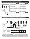
DA-1DS
DB-1MD
DB-1SD
DB-1MD/1SD
L L D E
L L D E
D
E
B1
B2
B3
B4
BL+
BL-
~~~
~~~
IER-2
TAR-3
PS
SW
A B
PS-0603DIN/0602C/0602D
I E
B1
B2
B3
B4
B1
B2
B3
B4
PT-1211DR/C/D
PT-1211DR/C/D
PT-1211DR/C/D
15V
2
4 4 4
4
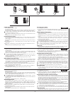
DB-1SD
DB-1SD
(1)
(2)
(3)(4)
DB-1MD
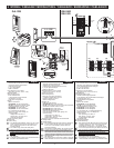
83.5mm
(3-5/16")
PT-1211DR
(230V)
PT-1211D
(230V)
PT-1211C
(120V)
DB-1SDDB-1SD DB-1SD
1
2
8mm
(3/8")
4
60mm
(2-3/8")
1,300mm
(4'3")
4
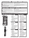
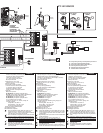
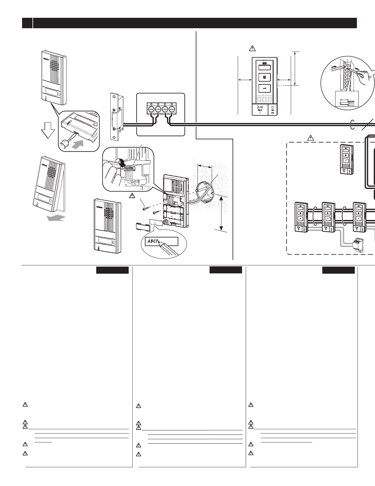
Press the tab and remove the front panel.
Connect the wires to the terminals.
Install on the gang box.
L, L: for door release.
D, E: for DB-1MD.
Door release: EL-12S or others
(More than (AC) 70 Ω, AC 9.5 ~ 20V)
Mounting bracket
Wood mounting screw
1. Press release button.
2. Insert the wire into the terminal.
Call extension or TAR-3
Lead wires: Orange/Yellow
Bell etc.
D,E: for door station.
B1,B2,B3,B4: for sub master station.
BL+,BL-: for request to exit/entry button
(Contact resistance: Less than 1KΩ)
B1,B2,B3,B4: for master station.
B1,B2,B3,B4: for sub master station.
PT-1211DR/C/D AC15V output
Option unit: Light, Gate, Garage, etc.
Contact (AC/DC)
Voltage Max.: 24V, Min.:1V
Current Max.: 1.6A, Min.:10mA
Lead wires: Brown/Red
Request to exit/entry button
A: Back wiring
B: Surface wiring
1. For DB-1MD/1SD installation, allow 5 cm (2") of open
space on either side of the unit and at least 15 cm
(6") of vertical open space from the center of the
mounting bracket.
2. For surface wiring, remove the cable jacket.
3. When connecting sub master stations, ID registration
setting is necessary for each sub master station.
(Refer to the ID setting instruction included with
DB-1SD.)
4. Not supplied (Wood mounting screws supplied with
DB-1MD/1SD)
5. To prevent shorts, be sure to cut unused lead wires at
the bottom and insulate the ends.
Auf die Lasche drücken und die vordere Abdeckung abnehmen.
Die Adern an die Klemmen anschließen.
An der Kabelanschlussdose anbringen.
L, L: für den Türöffner.
D, E: für das DB-1MD.
Türöffner: EL-12S oder andere
(Mindestens (AC) 70 Ω, AC 9,5 20 V)
Wandhalterung
Montageschraube für Holz
1. Die Klemmenentriegelung drücken.
2. Das Kabel an der Anschlussklemme befestigen.
Zusatzsignal oder TAR-3
Anschlussdrähte: Orange/Gelb
Klingel usw.
D,E: für die Türstelle.
B1,B2,B3,B4: für das Nebengerät.
BL+,BL-: für die Türfreigabe-Taste
(Kontaktwiderstand: höchstens 1 kΩ)
B1,B2,B3,B4: für das Hauptgerät.
B1,B2,B3,B4: für das Nebengerät.
PT-1211DR/C/D AC 15 V Ausgangsspannung
Optionales Gerät: Licht, Tor, Garage usw.
Kontakt (AC/DC)
Max. Spannung: 24V, Min.:1V
Max. Strom: 1,6A, Min.:10mA
Anschlussdrähte: Braun/Rot
Türfreigabe-Taste
A: Unterputzverdrahtung
B: Aufputzverdrahtung
1.
Beim Einbau des DB-1MD/1SD müssen rechts und links
der Anlage jeweils 5 cm sowie oberhalb und unterhalb
der Anlage mindestens 15 cm - von der Mitte der
Wandhalterung aus gemessen - frei gelassen werden.
2.
Im Falle einer Aufputzverdrahtung den Kabelmantel entfernen.
3. Beim Anschluss von Nebengeräten ist eine
Einstellung der ID-Registrierung für jedes Nebengerät
erforderlich. (Siehe die dem DB-1SD beiliegende
Anleitung zur ID-Einstellung.)
4. Nicht mitgeliefert (Mit dem DB-1MD/1SD werden
Montageschrauben für Holz geliefert)
5.
Zur Vermeidung von Kurzschlüssen unbedingt nicht
verwendete Adern abschneiden und die Enden isolieren.
Presione la pestaña y retírela del panel delantero.
Conecte los cables a las terminales.
Instale en la caja de montaje.
L, L: para la apertura de puertas.
D, E: para DB-1MD.
Abrepuertas: EL-12S u otros
(Más de (CA) 70 Ω, CA 9,5 20V)
Soporte de montaje
Tornillo para montaje en madera
1. Presione el botón release (Abrepuertas).
2. Inserte el cable en el terminal.
Extensión de llamada o TAR-3
Puntas de cable: Anaranjado/Amarillo
Timbre etc.
D,E: para el portero.
B1,B2,B3,B4: para aparato principal anexo.
BL+,BL-: para el botón para solicitar salida/entrada
(Resistencia de contacto: Menos de 1KΩ)
B1,B2,B3,B4: para aparato principal.
B1,B2,B3,B4: para aparato principal anexo.
PT-1211DR/C/D CA 15V salida
Unidad de opciones: Luz, Portón, Garaje, etc.
Contacto (CA/CC)
Voltaje Max.: 24V, Min.:1V
Corriente Max.: 1,6A, Min.:10mA
Puntas de cable: Marrón/Rojo
Botón para solicitar salida/entrada
A: Cableado posterior
B: Cableado de superficie
1. Para la instalación de DB-1MD/1SD, deje 5 cm de
espacio abierto en cualquiera de los lados de la
unidad y al menos 15 cm de espacio abierto vertical a
partir del centro del soporte de montaje.
2.
Para el cableado de superficie, quite el forro del cable.
3. Cuando conecte los aparatos principales anexos, es
necesario registrar el ID para cada aparato principal
anexo. (Consulte las instrucciones para registro de ID
que se incluyen con el DB-1SD.)
4. No incluido (Tornillos para montaje en madera
incluidos con el DB-1MD/1SD)
5. Para evitar cortocircuitos, asegúrese de cortar los
conductores principales sin usar en la parte inferior y
aislar las puntas.
Druk op het lipje en verwijder het frontpaneel.
Sluit de draden aan op de aansluitklemmen.
Installeer op de inbouwdoos (afzonderlijk te voorzien).
L, L: naar elektrisch deurslot.
D, E: naar DB-1MD.
Elektrisch deurslot: EL-12S of andere
(Meer dan (AC) 70 Ω, AC 9,5 20 V)
Montagesteun
Houtmontageschroef
1. Druk op de ontgrendelknop.
2. Steek de draad in de aansluitklem.
Extra bel of TAR-3
Aansluitdraden: Oranje/Geel
Deurbel, enz.
D,E: naar deurpost.
B1,B2,B3,B4: naar bijpost.
BL+,BL-: voor externe bediening deurslot
(contactweerstand: minder dan 1 KΩ)
B1,B2,B3,B4: naar hoofdpost.
B1,B2,B3,B4: naar bijpost.
transfo AC15V-uitgang
Optionele bediening: verlichting, hek, garage, enz.
Contact (AC/DC)
Spanning Max.: 24V, Min.:1V
Stroom Max.: 1,6A, Min.:10mA
Aansluitdraden: Bruin/Rood
Externe deurslotbediening
A: bekabeling in de muur
B: bekabeling boven op de muur
1. Laat bij de installatie van de DB-1MD/1SD 5 cm vrije
ruimte aan beide zijden van het toestel en ten minste
15 cm verticale vrije ruimte vanaf het midden van de
montagesteun.
2. Bij bedrading boven op de muur moet de kabelmantel
worden verwijderd.
3. Wanneer bijposten worden aangesloten, is
ID-registratie nodig voor elke bijpost. (Zie de
aanwijzingen voor het instellen van het ID-nummer in
de handleiding van de DB-1SD)
4. Niet bijgeleverd (Houtmontageschroeven bijgeleverd
bij de DB-1MD/1SD)
5.
Om kortsluitingen te voorkomen, moeten ongebruikte
draden aan de uiteinden worden afgeknipt en geïsoleerd.
Premere la linguetta e rimuovere il pannello frontale.
Collegare i cavi ai terminali.
Montare sopra il contenitore multiplo.
L, L: per attivazione dell’apriporta.
D, E: per DB-1MD.
Apriporta: EL-12S o altri
(Più di (CA) 70 Ω, CA 9,5 20 V)
Staffa di montaggio
Vite di montaggio per legno
1. Premere il pulsante di sganciamento.
2. Inserire il cavo nel terminale.
Prolunga chiamata o TAR-3
Cavi principali: Arancione/Giallo
Campanello, ecc.
D,E: per postazione esterna.
B1,B2,B3,B4: per postazione secondaria.
BL+,BL-: per tasto richiesta di entrata/uscita
(Resistenza contatti: meno di 1 KΩ)
B1,B2,B3,B4: per postazione principale.
B1,B2,B3,B4: per postazione secondaria.
PT-1211DR/C/D uscita CA 15 V
Unità opzioni: Luce, cancello, garage, ecc.
Contatto (CA/CC)
Tensione Max.: 24V, Min.:1V
Corrente Max.: 1,6A, Min.:10mA
Cavi principali: Marrone/Rosso
Tasto richiesta di entrata/uscita
A: Cablaggio posteriore
B: Cablaggio superficiale
1. Per il montaggio di DB-1MD/1SD, lasciare 5 cm di
spazio su uno dei lati dell’unità e almeno 15 cm di
spazio verticale dal centro della staffa di montaggio.
2. Per il cablaggio superficiale, rimuovere la guaina del
cavo.
3. Quando si collegano le stazioni secondarie, è
necessaria per ogni stazione l’impostazione di
registrazione ID. (Vedere le istruzioni di impostazione
ID incluse nel DB-1SD)
4. Non fornite (Viti di montaggio per legno fornite con
DB-1MD/1SD)
5. Per evitare cortocircuiti, ricordare di tagliare i
conduttori inutilizzati al fondo e di isolarne le
estremità.
English
Français
Deutsch
NederlandsEspañol Italiano
WIRING / CABLAGE/ VERDRAHTUNG / CABLEADO / BEDRADING / CABLAGGIO
Appuyez sur la languette et ôtez la face avant.
Branchez les fils sur les bornes.
Installez la boite d'encastrement(non fourni).
L, L: pour gâche électrique.
D, E: pour DB-1MD.
Gâche électrique: EL-12S ou autres
(Plus de 70 Ω (CA), 9,5 20V CA)
Support de montage
Vis de montage à bois
1. Appuyez sur le bouton d'ouverture.
2. Introduire le câble dans la borne.
Extension d'appel ou TAR-3
Câbles: Orange/Jaune
Sonnette, etc.
D,E: pour poste de porte.
B1,B2,B3,B4: pour poste secondaire.
BL+,BL-: pour requête envoyée vers le bouton de sortie/d'entrée
(résistance de contact: moins de 1KΩ)
B1,B2,B3,B4: pour poste maître.
B1,B2,B3,B4: pour poste secondaire.
Sortie PT-1211DR/C/D CA15V
Unité optionnelle: Lumière, grille, garage, etc.
Contact (CA/CC)
Tension Max.: 24V, Min.:1V
Courant Max.: 1,6A, Min.:10mA
Câbles: Marron/Rouge
Requête envoyée vers le bouton de sortie/d'entrée
A: Câblage arrière
B: Câblage saillant
1. Pour installer le DB-1MD/1SD, laissez un espace de
5 cm de chaque côté de l'unité et un espace d'au
moins 15 cm à la verticale à partir du centre du
support de montage.
2.
Pour brancher le câble saillant, ôtez la gaine du câble.
3.
Lorsque vous branchez des postes secondaires, veillez à
régler les paramètres d'enregistrement d'identifiant pour
chaque poste secondaire. (Veuillez consulter les instructions
relatives au réglage de l'identifiant fournies avec la DB-1SD.)
4. Non fourni (Vis de montage à bois fournies avec le
DB-1MD/1SD)
5.
Pour empêcher les courts-circuits, veillez à couper les
câbles inutilisés dans le fond et à isoler les extrémités.
Polarized
Polarisé
Polarität beachten
Polarizado
Gepolariseerd
Polarizzato
OR: Orange/Orange/Orange/Anaranjado/Oranje/Arancione
YE: Yellow/Jaune/Gelb/Amarillo/Geel/Giallo
BR: Brown/Marron/Braun/Marrón/Bruin/Marrone
RD: Red/Rouge/Rot/Rojo/Rood/Rosso
BK: Black/Noir/Schwarz/Negro/Zwart/Nero
BL: Blue/Bleu/Blau/Azul/Blauw/Blu
- 4 -