


11
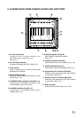
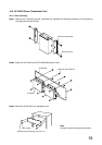
8. AI-900MF MAIN FRAME NOMENCLATURE AND FUNCTIONS
1
2
3
4
5
6 7 8
9
10
11
12
1. AC Input Connectors
Connect to the AC output terminal of the
AI-PU200 power transformer unit.
(See p. 39.)
2. 24 V DC Input Connector
Connects to a battery (24 V DC). (See p. 39.)
3. Power Switch
Power is switched on (I) and off (O) with each
depression of this switch.
4. Backup Battery Socket
Insert the CR2032 data backup battery into this
socket. (See p. 19.)
5.
AI-900MS/AI-900AL Installation Slot [MS/AL 1-2]
A maximum of 2 AI-900MS or AI-900AL cards
can be installed. (See p. 24 and 29.)
6. AI-900RS Installation Slot [RS 1-4]
A maximum of 4 AI-900RS cards can be
installed. (See p. 30.)
7.AI-900CO Installation Slot [CO]
One AI-900CO card can be installed.
(See p. 32.)
8. AI-900AF Installation Slot [AF]
One AI-900AF card can be installed. (See p. 34.)
9. AI-900TI Installation Slot [TI]
One AI-900TI card can be installed. (See p. 36.)
10. Programming PC Connector [RS-232C]
Connects to the programming PC either directly
or via modem. (See p. 40.)
11. Operation Log PC Connector [RS-232C]
Connects to the operation log PC either directly
or via modem. (See p. 42.)
12. Power Indicator
Lights when the power switch is set to ON.