


HEARTH REQUIREMENTS
To comply with current Building Regulations the
fire must stand on a fireproof hearth, which has an
upper fireproof layer of 12mm non-combustible
material. If the rear of the fire is to be pushed up
against a surface it must be of a non-combustible
material.
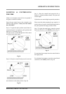
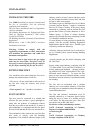
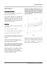
The hearth must protrude at least 25mm in front of
the glass window and 150mm either side.
The hearth must not be capable of inadvertent
covering by a carpet or rug. This should be
achieved by either:
The hearth being 50mm above the level of the room
floor. A 50mm high fender or kerb being fixed
around the edge of the hearth.
CONNECTING THE GAS SUPPLY
Once the fire is in place it is then possible to
connect the gas supply. The gas supply point is
located at the rear of the appliance and should be
connected in accordance with the following
requirements.
Check that the appliance is suitable for the gas
supply; refer to data labels on packaging and/or the
fire for gas type. Note: Natural gas and Propane
(LPG) models are not interchangeable.
The gas installation must be in accordance with the
current issue of BS6891.Gas supply pressure at the
fire should be 20mbar for natural gas.
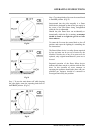
The gas supply should be connected with the
1/4"BSP nut and olive with 8mm tubing.
A maximum pipe run of 1.5 meters (or 5 feet)
should be adhered to and copper tubing may be
used provided a distance of 25mm is maintained
between pipe-work and any surface of the fire. A
gas service cock should be fitted adjacent to the
fireplace to enable safe removal of the appliance for
servicing. After fitting the supply, operate the gas
cock (supplied) and check all joints up to the
termination of the supply pipe for gas tightness
using a soap/water solution and the pressure drop
method.
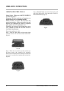
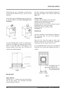
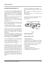
To check the pressure to the burner it is
necessary to ignite the appliance and set to 'high
rate'.
This is carried out by following instructions on
pages 9 and 10.
Cold setting pressures are in the Technical data
section on page 6.
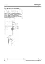
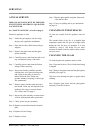
The pressure test point is located through the hole
in the valve bracket marked 'test point',
See Fig.8 below.
Fig. 8
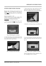
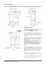
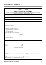
TEST SEQUENCE
ENSURE FIRE IS OFF
1. Open control door.
2. Loosen test point screw.
3. Connect hose of test equipment to test point
through the test point hole in bracket. (If necessary
open fire door and remove coal set, base matrix
plate and heatsheild. Close door on completion)
4. Turn on fire and set flame on high.
5. Take reading.
6. Turn fire off.
7. Remove test equipment hose.
8. Re-tighten test screw (If necessary replace
heatsheild, matrix plate and coal set.
Becton Bunny & Becton 7 mk3 Gas stoves 15
INSTALLATION
Pressure test
point