


Installation
Identify a suitable location for the vertical lifeline anchorage connection. Anchorages must be capable of meeting the
strength requirements of OSHA 29 CFR 1919.66 and 1926.502. Connect anchorage connector of vertical lifeline to approved
anchorage. The vertical lifeline must be installed as vertically as possible over the intended work area to reduce the possibility
of dangerous swing falls.
Caution: Installer may be exposed to a fall hazard during installation. Alternate safety equipment may be required during
installation.
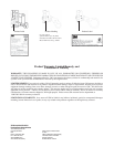
For Part Numbers 123, 124, 129
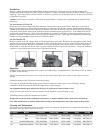
Ensure the vertical lifeline hangs freely from anchorage without twists or knots in the lifeline. With arrow on the body of
the Fall Arrester pointing up, pull security latch handle up to release the rope chamber. Unscrew thumbscrew knob until the
chamber opens. Insert vertical lifeline rope into the chamber. The arrow on the body of the Fall Arrester MUST point upwards
towards the vertical lifeline anchor point. Position back half of chamber around rope and close. Screw thumbscrew into the
receiving nut until thumbscrew is tight. Secure the chamber by grasping the small knob on the security latch moving it into
position in the notch. Compress the Fall Arrester upwards to position on rope. Attach approved compatible personal energy
absorber or energy absorbing lanyard to the eye of the Fall Arrester.
For Part Number 128
Remove carabiner from 128. Support body of 128 and lift handle to open cams. Holding in the open position, rotate 128 90°
and slide the slot over the M400 cable. Rotate back to vertical with cable laying in grooves of the 128. The arrow on the 128
MUST be pointed upward. Release the cam handle to close cam against the cable. Insert carabiner into hole at the bottom
of the handle to secure the 128 onto the cable. Connect carabiner to front D-ring of full body harness. Do not add additional
connectors to extend the distance between the 128 and the front D-ring.
Inspection
All Fall Arresters must be inspected prior to each use, and additionally a “competent person” (other than the user), as defi ned
by OSHA, at least annually.
All rope must be inspected for tears, cuts, fraying, abrasion, discoloration, burns, holes, mold, or other signs of wear and
damage.
Orientation lockout on the 128 must be functioning properly.
Cable must be inspected for kinks, broken strands, corrosion, abrasion, or other signs of wear and damage. Swaged
terminations should be secure with the thimble tight, and not visibly damaged.
Any equipment that has been subjected to the forces of a fall must be removed from service.
All Fall Arresters must be free of corrosion, chemical attack, alteration, excessive heating or wear.
All markings must be legible and attached to the product.
If inspection reveals any defect, inadequate maintenance, or unsafe condition, remove from service and destroy.
Note: Only manufacturer, or entities authorized in writing by the manufacturer, may make repairs to the product.
Cleaning and Maintenance
Fall Arresters can be wiped down with a dry cloth to remove dirt and grease. No maintenance is required for this product. If
inspection reveals any defect, remove from service.
Part Number Material Lifeline Size Connector Size Capacity Weight Standard
123 Steel 5/8 in. (16mm) Rope 2 in. (53mm) 400 lbs. (181kg) 1.1 lbs. (505g) ANSI Z359.1-07
124 Steel 5/8 in. (16mm) Rope 0.88 in. (23 mm) 400 lbs. (181kg) 1.1 lbs. (524g) ANSI Z359.1-07
129 303 & 304 Stainless Steel 5/8 in. (16mm) Rope 2.1 in. (54 mm) 400 lbs. (181kg) 1.1 lbs. (505g) ANSI Z359.1-07
128 Stainless Steel and Brass 3/8 in. (10mm) Cable 0.78 in. (20mm) 310 lbs. (140kg) 1.5 lbs. (684g) ANSI Z359.1-07