


035-16328-092 Rev. C (0902)
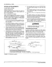
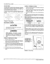
CEILING RINGS
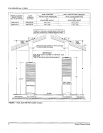
The coiling ring is to meet fire stop requirements. Accessory
Ceiling Ring (PIN 7660-2841) may be used, (See Figure 15)
or the manufactured home manufacturer or the installer may
use other approved methods to stop fire.
CONNECT THERMOSTAT WIRES
1. Insert24 voltwires throughthe smallplasticbushing just
above the control panel.
2.
If required, three (3) sections of Accossory Ring may be used
as shown in Figure 15 to provide closer clearance around 3.
roof jack,
A B
FIGURE 15 : Ceiling Rings
ELECTRICAL WIRING
IlIA CAUTIiQN
TO INSTALLER: Incoming power must be polar-
ized. Observe color coding.
AWARNING!
SHOCK HAZARD - DISCONNECT ELECTRI-
CAL POWER SUPPLY TO THE UNIT BEFORE
SERVICING TO AVOID THE POSSIBILITY OF
SHOCK INJURY OR DAMAGE TO THE EQUIP-
MENT
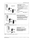
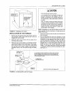
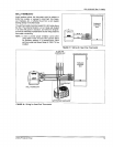
CONNECT POWER SUPPLY WIRES
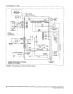
1. Remove the field wiringcover.
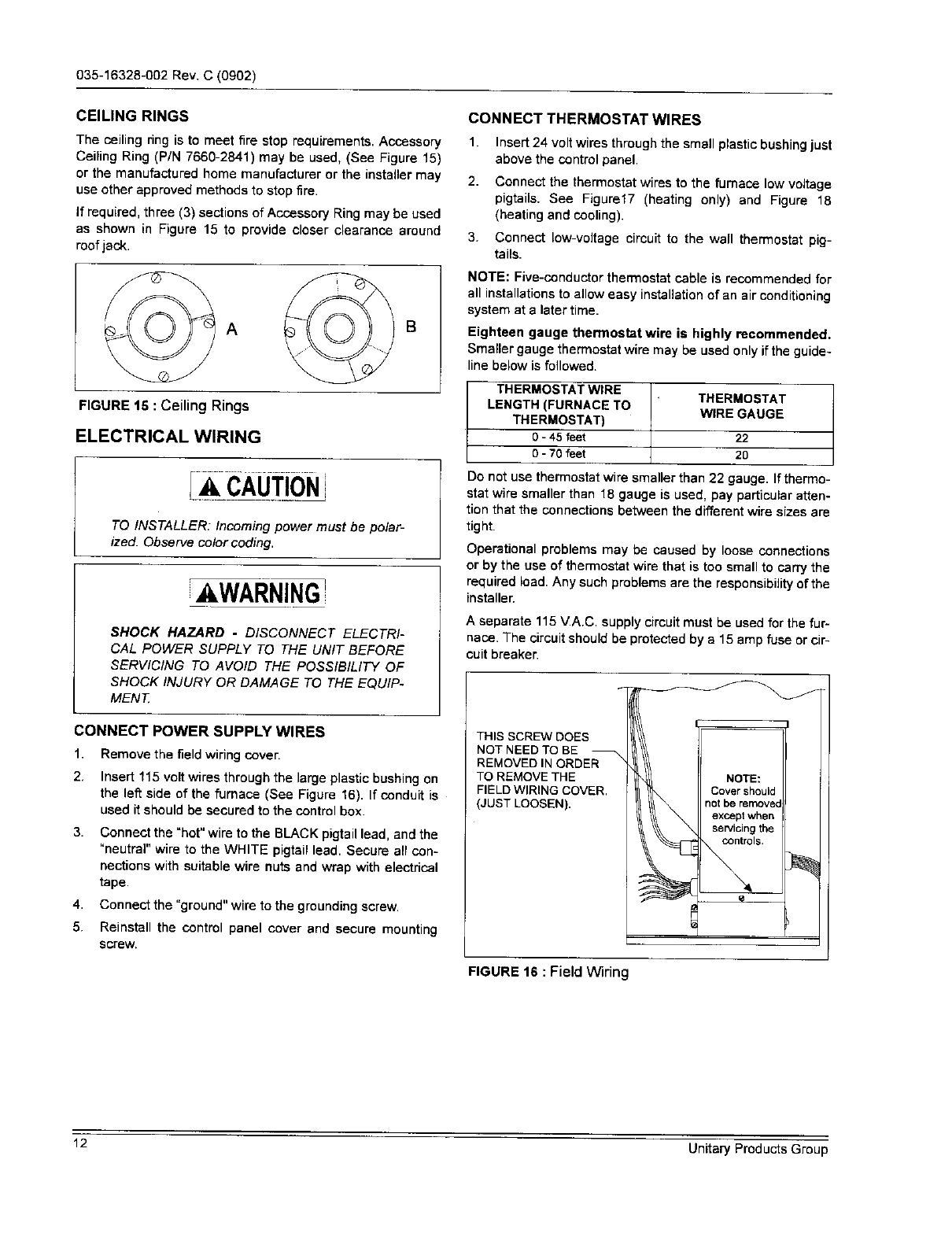
2, Insert 115 volt wires through the large plastic bushing on
the left side of the furnace (See Figure 16). If conduit is
used it should be secured to the control box.
3.
Connect the "hot" wire to the BLACK pigtail lead, and the
"neutral" wire to the WHITE pigtail lead. Secure all con-
nections with suitable wire nuts and wrap with electrical
tape.
4. Connect the "ground" wire to the grounding screw.
5. Reinstall the control panel cover and secure mounting
screw,
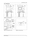
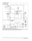
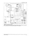
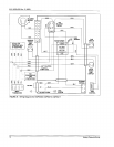
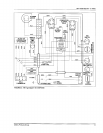
Connect the thermostatwires to the furnace low voltage
pigtails. See Figure17 (heating only) and Figure 18
(heating and cooling).
Connect low-voltage circuit to the wall thermostat pig-
tails.
NOTE: Five-conductorthermostat cable is recommended for
all installations to allow easy installation of an air conditioning
system at a later time.
Eighteen gauge thermostat wire is highly recommended.
Smaller gauge thermostatwire may be usedonly ifthe guide-
linebelow isfollowed.
THERMOSTAT WIRE
LENGTH (FURNACE TO
THERMOSTAT)
0 - 45 feet
0 - 70 feet
THERMOSTAT
WlRE GAUGE
22
20
Do not use thermostat wire smaller than 22 gauge. Ifthermo-
stat wire smaller than 18 gauge is used, pay particular atten-
tion that the connections between the different wire sizes are
tight.
Operational problems may be caused by loose connections
or by the use of thermostat wire that istoo small to carry the
required load. Any such problems are the responsibility of the
installer.
A separate 115_/A.C. supplycircuitmust be usedfor the fur-
naco. The circuit shouldbe protected by a 15 amp fuse or cir-
cuit breaker.
J
THIS SCREW DOES
NOT NEED TO BE
REMOVED IN ORDER
TO REMOVE THE
FIELD WIRING COVER.
(JUST LOOSEN).
NOTE:
Cover should
not be removed
except when
servicing the
controls.
a
FIGURE 16 : Field Wiring
12 Unitary Products Group