


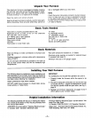
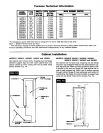
Furnace Technical Information
MODEl. TYPE INPUT *
NUIBMm GAS RATING
IrTU/NR
1403612 NAT. 14,000
1403611 L.P.G. 14,000
1403622 NAT. 14,000
1403621 LP.G. 14,000
2203612 NAT. 22,000
2203611 LP.G. 22,000
2203622 NAT. 22,000
2203621 LP.G. 22,000
3003612 NAT. 30,000
3003611 LP.G. 30,000
3003622 NAT. 30,000
3003621 LP.G. 30,000
HTG. CAPAO.
RATING
IITU/IHfl
10,039
10,039
10,039
10,039
16,462
16,462
16,462
16,462
21,849
21,849
21,849
21,849
MAIN BURNER OfliPJC8
DILL DEC. QTY.
#51 0670
#58 .0420
#51 .0670
#58 .0420
#45 .0820
#55 .0520
#45 .0820
#55 .0520
#42 .0935
#53 .0595
#42 .0935
#53 .0595
*For elevations above 2000 feet reduce ratings 4% for each 1000 feet above sea level.
Btuh = British Thermal Units per hour.
The efficiency ratging of these appliances is a product thermal efficiency rating system determined under con-
tinuous operating conditions and was determined independently of any installed system.
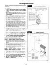
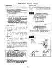
Cabinet Installation
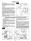
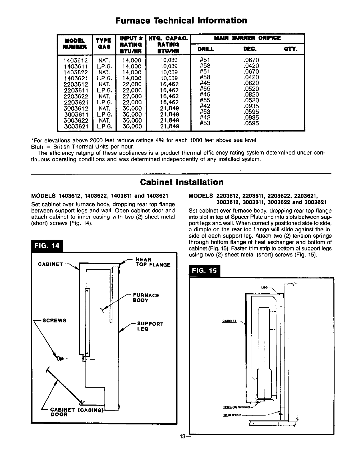
MODELS 1403612, 1403622, 1403611 and 1403621
Set cabinet over furnace body, dropping rear top flange
between support legs and wall. Open cabinet door and
attach cabinet to inner casing with two (2) sheet metal
(short) screws (Fig. 14).
REAR
CABINET _ "_'m-p'p'p'p'p'p'p_ TOP FLANGE
-Hr
BINET (CASING)
DOOR
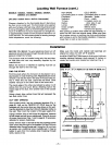
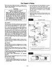
MODELS 2203612, 2203611, 2203622, 2203621,
3003612, 3003611, 3003622 and 3003621
Set cabinet over furnace body, dropping rear top flange
into slot in top of Spacer Plate and into slots between sup-
port legs and wall. When correctly positioned side to side,
a dimple on the rear top flange will slide against the in-
side of each support leg. Attach two (2) tension springs
through bottom flange of heat exchanger and bottom of
cabinet (Fig. 15). Fasten trim strip to bottom of support legs
using two (2) sheet metal (short) screws (Fig. 15).
CABINET -- i :
i
i
I
I
T__ _
--13--: