


Thermostat Installation (cont.)
6. Snag thermostat cable through wall so that 6 inches
of cable protrudes.
7. Route cable to wall furnace leaving enough excess
cable to make the connections at the gas valve.
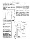
MOUNTING THE THERMOSTAT
1. To remove the thermostat cover, grasp cover and pull
straight outward. Carefully remove and discard the
packing tab protecting the switch contacts.
2. Connect thermostat wires to the terminal screws on the
back of thermostat base.
3. Push any excess wire back through hole in wall and
plug hole with insulation to prevent drafts from affect-
ing thermostat operation.
4. Being sure to level thermostat for best appearance,
fasten thermostat base to wall through mounting holes
with screws provided.
5. Replace the thermostat cover.
NOTE
Refer to installation instructions packed in the thermostat
carton if you have any doubt about the above procedures.
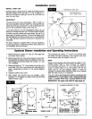
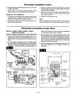
Thermostat Connection at Gas Valve
MODELS 1403622, 1403621, 2203622, 2203621,
3003622 and 3003621
(All other models are equipped with a built-in thermostat)
1. If an old thermostat is being replaced and is in a
satisfactory location and the wiring appears to be in
good condition, use existing wiring. If in doubt, use new
wire.
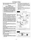
2. If a new location is chosen or if this is a new installa-
tion, thermostat cable must first be run to the location
selected. All wiring must agree with local codes and
ordinances. These instructions cover bringing the wire
3.
4.
down from the attic but it can be run from a basement
or crawl space using similar methods.
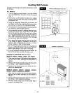
Before drilling hole in wall at selected location, drive
a small finishing nail through the ceiling in the corner
of the wall and ceiling above the thermostat location.
Pull the nail out and push a small stiffwire through the
hole so itcan be found in the attic. Drill a 1/2 inch hole
through the ceiling wall plate.
Probe for obstructions in the partition. Then drill a 1/2
inch hole through wall at selected location for
thermostat.
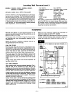
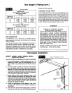
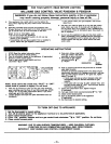
THERMOSTAT GENERATOR
£D WIRE WHI'I_ WIRE
1
V LUAMS
P121200
(OR) _)¢mm.o _
P171600 JUMPER
WILUAMS P295200A (OR) P295201A
GENERATOR THERMOSTAT
GREEN KNOB
INNER CASING
(r _) _i SHIELD
PILOT
OBSERVATION
DOOR
(:PEEP-HOLE
COVER)
DOOR
GROUND
JOINT UNION
FITTING
DRIP LEG
WIRES
-MANUAL
SPARK
iGNITOR
PRESS
REPEATEDLY
CONTROL
VALVE
MANUAL
SHUT-OFF
VALVE
RG. 13
--12--