


Gas Supply & Piping (cont.)
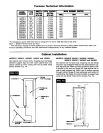
GAS PtPE SIZES
NATURAL GAS
PIPE CAPACITY - BTU PER HOUR
(INCLUDES FITTINGS)
PIPE SIZE
LENGTH OF
PIPE - FEET 1/2 inch 3/4 inch 1 inch
20 92,000 190,000 350,000
40 63,000 130,000 245,000
60 50,000 105,000 195,000
L.P. GAS
PIPE CAPACITY - BTU PER HOUR
(INCLUDES FITTINGS)
LENGTH OF
PIPE - FEET 112 inch 3/4 inch 1 inch
20 189,000 393,000 732,000
40 129,000 267,000 504,000
60 103,000 217,000 409,000
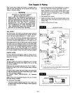
GAS CONNECTION
If installation is for L.P. Gas have L.P. installer use two-
stage regulation and make all connections from storage
tank to furnace.
Use two pipe wrenches when making the connection to
the valve to prevent turning or damage to gas valve.
Connection between shut off valve and burner control
assembly can be made with an A.G.A./C.G.A. design cer-
tified flexible connector if allowed by local codes.
Tighten all joints securely.
CHECKING THE GAS PIPING
Test all piping for leaks. When checking gas piping to the
furnace with gas pressure at less than 1/2 PSI, shut off
manual gas valve for the furnace. If gas piping is to be
checked with the pressure at or above 1/2 PSI, the furnace
and manual shut off valve must be disconnected during
testing. (SEE WARNING BELOW.) Apply soap suds (or
a liquid detergent) to each joint. Bubbles forming indicates
a leak. Correct even the slightest leak at once.
WARNING
DANGER OF PROPERTY DAMAGE,
BODILY INJURY OR DEATH.
NEVER USE A MATCH OR OPEN FLAME TO TEST
FOR LEAKS. NEVER EXCEED SPECIFIED
PRESSURES FOR TESTING. HIGH PRESSURES
MAY DAMAGE THE GAS VALVE AND CAUSE
OVER-FIRING WHICH MAY RESULT IN HEAT EX-
CHANGER FAILURE. LIQUID PETROLEUM (L.P.)
GAS IS HEAVIER THAN AIR AND IT WILL SE'I-FLE
IN ANY LOW AREA, INCLUDING OPEN DEPRES-
SION AND IT WILL REMAIN THERE UNLESS
AREA IS VENTILATED.
NEVER ATTEMPT START-UP OF UNIT BEFORE
THOROUGHLY VENTILATING AREA.
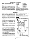
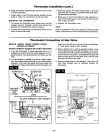
Thermostat Installation
MODELS 1403622, 1403621, 2203622, 2203621,
3003622 and 3003621
(All other models are equipped with a built-in thermostat)
1. If an old thermostat is being replaced and is in'a
satisfactory location and the wiring appears to be in
good condition, use existing wiring. If indoubt, use new
wire.
2. If a new location is chosen or if this is a new installa-
tion, thermostat cable must first be run to the location
selected. All wiring must agree with local codes and
ordinances. These instructions cover bringing the wire
down from the attic but it can be run from a basement
or crawl space using similar methods.
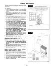
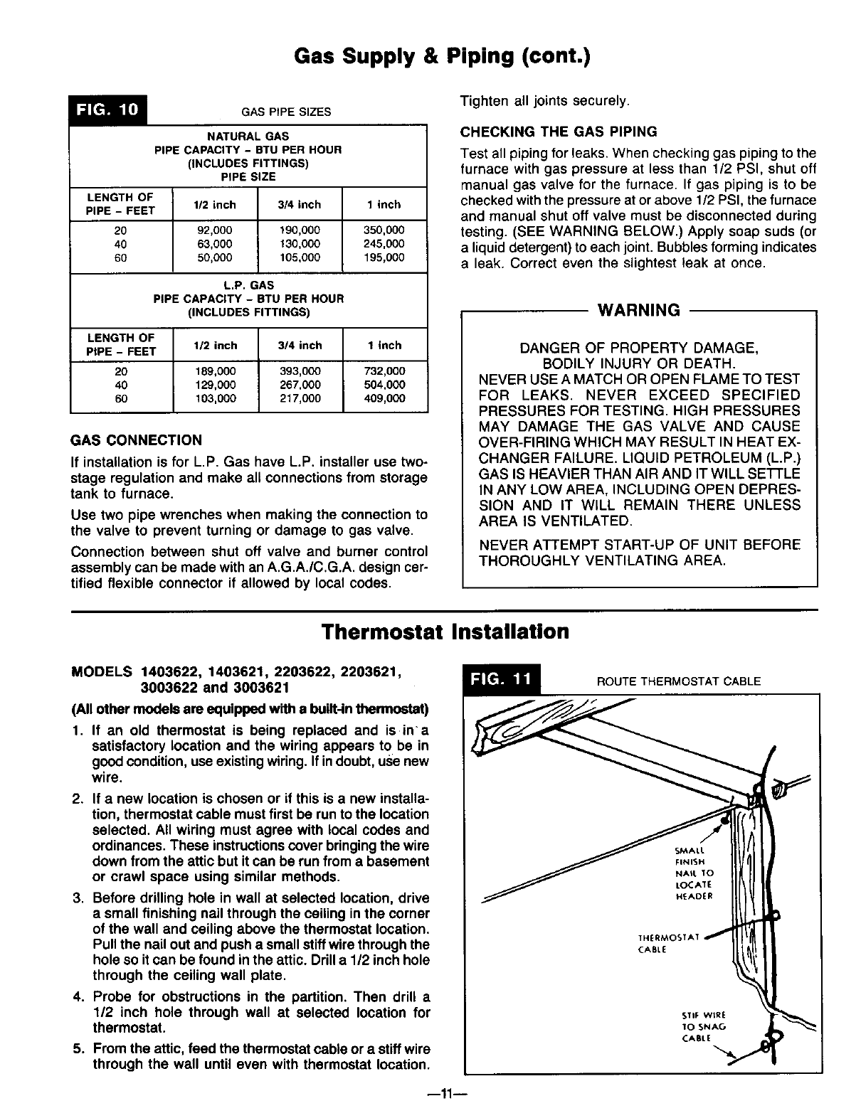
3. Before drilling hole in wall at selected location, drive
a small finishing nail through the ceiling in the corner
of the wall and ceiling above the thermostat location.
Pull the nail out and push a small stiffwire through the
hole so itcan be found in the attic. Drill a 1/2 inch hole
through the ceiling wall plate.
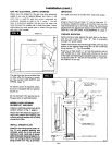
4. Probe for obstructions in the partition. Then drill a
112 inch hole through wall at selected location for
thermostat.
5. From the attic, feed the thermostat cable or a stiff wire
through the wall until even with thermostat location.
ROUTE THERMOSTAT CABLE
SMAL I.
FINISH
NAi l, 10
LOCATE
H_ADER
CABL[
STIF WtRE
10 SNAG
CABLE
--11 m