


3
CHECK THERMOSTAT OPERATION
If at any time during testing your system does not operate
properly, contact a qualified serviceperson.
Fan Operation
If your system does not have a G terminal connection, skip to
Heating System.
1. Turn on power to the system.
2. Move FAN switch to ON position. The blower should begin
to operate.
3. Move FAN switch to AUTO position. The blower should stop
immediately.
Heating System
1. Move SYSTEM switch to HEAT position. If the heating
system has a standing pilot, be sure to light it.
2. Press to adjust thermostat setting above room tempera-
ture. The heating system should begin to operate.
3. Press to adjust temperature setting below room tempera-
ture. The heating system should stop operating.
Cooling System
This thermostat has a built-in short-term (5-minute) time delay.
This feature is activated after the compressor shuts down and
the setpoint is changed within the 5-minute period. During this
5-minute period, COOL will flash on the display indicating that
the thermostat has locked out the compressor to allow head
pressure to stabilize. This thermostat does not sense AC power
loss and therefore does not activate the short term compressor
protection feature when power is restored.
To prevent compressor and/or property damage, if the
outdoor temperature is below 50°F, DO NOT operate
the cooling system.
1. Move SYSTEM switch to COOL position.
2. Press to adjust thermostat setting below room tempera-
ture. The blower should come on immediately on high speed,
followed by cold air circulation
3. Press to adjust temperature setting above room tempera-
ture. The cooling system should stop operating.
RH
Y
24 VAC
120 VAC
Hot
Neutral
THERMOSTAT
SYSTEM
G W
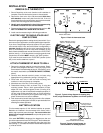
Figure 5. Typical wiring diagram for
heat only, 3-wire, single transformer systems
TRANSFORMER
Heating
System
Fan
Relay
Y
RC
JUMPER
WIRE
RED jumper wire (provided
with thermostat) must be
connected between thermo-
stat's RH and RC terminals
for proper thermostat oper-
ation with this system.
NOTE
OB
RH
Y
24 VAC
120 VAC
Hot
Neutral
THERMOSTAT
SYSTEM
G W
Figure 6. Typical wiring diagram for
cool only, 3-wire, single transformer systems
Cooling
System
Fan
Relay
RCOB
RH
Y
24 VAC
120 VAC
Hot
Neutral
THERMOSTAT
SYSTEM
G W
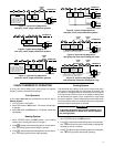
Figure 7. Typical wiring diagram for
heat/cool, 4-wire, single transformer systems
TRANSFORMER
Heating
System
Fan
Relay
Cooling
System
RC
JUMPER
WIRE
RED jumper wire (provided
with thermostat) must be
connected between thermo-
stat's RH and RC terminals
for proper thermostat oper-
ation with this system.
NOTE
OB
RH
Y
24 VAC
120 VAC
Hot
Neutral
THERMOSTAT
SYSTEM
G W
Figure 10. Typical wiring diagram for
heat pump with heat active changeover relay
TRANSFORMER
Changeover
Relay*
RCOB
JUMPER
WIRE
Compressor
Contactor
JUMPER
WIRE
* Changeover Relay is energized when the
system switch is in the HEAT position
Fan
Relay
RH
Y
24 VAC
120 VAC
Hot
Neutral
THERMOSTAT
SYSTEM
G W
Figure 9. Typical wiring diagram for
heat pump with cool active changeover relay
TRANSFORMER
Changeover
Relay*
RCOB
JUMPER
WIRE
Compressor
Contactor
JUMPER
WIRE
* Changeover relay is energized when the
system switch is in the COOL position
Fan
Relay
RH
Y
24 VAC
120 VAC
Hot
Neutral
THERMOSTAT
SYSTEM
G W
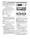
Figure 8. Typical wiring diagram for
heat/cool, 5-wire, two-transformer systems
HEATING TRANSFORMER
Heating
System
Fan
Relay
Cooling
System
RC
24 VAC
120 VAC
Hot
Neutral
COOLING TRANSFORMER
OB
CAUTION
!