


24
Removing and Replacing the Gas
Control Valve/Thermostat
IMPORTANT: The gas control valve/thermostat is a standard
valve with wire leads that connect to a thermal switch.
Removing the Gas Valve:
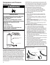
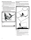
1. On the gas control valve/thermostat turn the temperature
dial counterclockwise to its lowest setting. Depress the
dial stop and turn the gas control knob clockwise to the
“OFF” position (Figure 19).
2. Turn off the gas at the manual shut-off valve on the gas
supply pipe (Figure 3).
3. Drain the water heater. Refer to the section of Draining
and Flushing and follow the procedure.
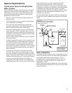
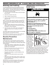
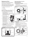
4. Disconnect the igniter wire from the igniter button.
Remove the igniter button by depressing front and rear
holding tabs and lift. Remove igniter bracket. Disconnect
the thermocouple (right-hand threads), pilot tube, two
wire leads at the thermal switch, and manifold tube at
the gas control valve/thermostat (Figure 22). NOTE:
L.P. gas systems use reverse (left-hand) threads on the
manifold tube.
5. Refer to “Gas Piping” (Figure 3) and disconnect the
ground joint union in the gas piping. Disconnect the
remaining pipe from the gas control valve/thermostat.
6. To remove the gas valve, thread a correctly sized
Flame Lock
™
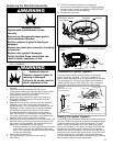
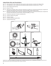
Safety System Operational Checklist
TROUBLESHOOTING CHART
pipe into the inlet and use it to turn the gas valve
(counterclockwise.) Do not use pipe wrench or
equivalent to grip body. Damage may result, causing
leaks. Do not insert any sharp objects into the inlet or
outlet connections. Damage to the gas valve may result.
Replacing the Gas Valve:
To replace the gas control valve/thermostat, reassemble in
reverse order. This water heater has a resettable thermal
switch installed. DO NOT attempt to disable or modify this
feature in any way. When replacing the gas valve, thread a
correctly sized pipe into the inlet and use it to turn the gas
valve (clockwise.) DO NOT OVER TIGHTEN, damage may
result.
• Be sure to use approved Teflon
®
tape or pipe joint
compound on the gas piping connections and fitting on
the back of the gas control valve that screws into tank.
• Be sure to remove the pilot ferrule nut from the new gas
control valve/thermostat.
• Turn the gas supply on and check for leaks. Test all
connections by brushing on an approved noncorrosive
leak-detection solution. Bubbles will show a leak.
Correct any leak found.
• Be sure tank is completely filled with water before
lighting and activating the water heater. Follow the
Lighting Instructions.
• If additional information is required, contact the Service
Department at: 1-877-817-6750.
TEFLON is a registered trademark of E.I. Du Pont De Nemours and Company.
5. No leaks at pilot and manifold connection.
6. Manifold door screws securely tightened.
7. Depress the button on the thermal switch.
1. Manifold gasket properly sealed.
2. Viewport not damaged or cracked.
3. Flame-trap free of debris and undamaged.
4. Two piece wire connector properly installed.
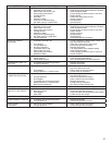
PROBLEM POSSIBLE CAUSE(S) CORRECTIVE ACTION
BURNER WILL NOT IGNITE 1. Pilot not lit
2. Thermostat set too low
3. No gas
4. Dirt in the gas lines
5. Pilot line clogged
6. Main burner line clogged
7. Non-functioning thermocouple
8. Non-functioning thermostat
9. Heater installed in a confined area
1. Light pilot
2. Turn temp. dial to desired temperature
3. Check with gas utility company
4. Notify utility-install trap in gas line
5. Clean, locate source and correct
6. Clean, locate source and correct
7. Replace thermocouple
8. Replace thermostat
9. Provide fresh air ventilation
SMELLY WATER 1. Sulfides in the water 1. Replace the anode with a special anode
BURNER FLAME YELLOW-
LAZY
1. Insufficient secondary air
2. Low gas pressure
3. Flue clogged
4. Main burner line clogged
5. Heater installed in a confined area
6. Obstruction in main burner orifice
1. Provide ventilation to water heater
2. Check with gas utility company
3. Clean, locate source and correct
4. Clean, locate source and correct
5. Proper fresh air ventilation
6. Clean or replace orifice
PILOT WILL NOT LIGHT OR
REMAIN LIT
1. Non-functioning igniter
2. The thermal switch tripped
3. Thermocouple connection loose
4. Air in gas line
5. Low gas pressure
6. No gas
7. Dirt in gas lines
8. Cold drafts
9. Thermostat ECO switch open
10. Pilot line or orifice clogged
11. Non-functioning thermocouple
12. Air for combustion obstructed
13. Flammable vapors incident, Flame Lock
™
function utilized
1. Replace igniter pilot assembly
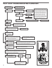
2. See Pilot Light Troubleshooting Flowchart
section
3. Finger tighten; then 1/4 turn with wrench
4. Bleed the air from the gas line
5. Check with gas utility company
6. Check with gas utility company
7. Notify utility-install dirt trap in gas line
8. Locate source and correct
9. Replace thermostat
10. Clean, locate source and correct
11. Replace thermocouple
12. See maintenance section for inspection and
cleaning of flame trap
13. Replace water heater, eliminate flammable
vapors source. Call 1-877-817-6750