


14
Temperature and Pressure
Relief Valve
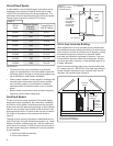
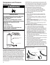
For protection against excessive pressures and
temperatures, a temperature and pressure relief valve must
be installed in the opening marked “T & P RELIEF VALVE”
(see Figure 15A). This valve must be design certified by
a nationally recognized testing laboratory that maintains
periodic inspection of the production of listed equipment or
materials as meeting the requirements for Relief Valves and
Automatic Shut-off Devices for Hot Water Supply Systems,
ANSI Z21.22. The function of the temperature and pressure
relief valve is to discharge water in large quantities in the
event of excessive temperature or pressure developing
in the water heater. The valve’s relief pressure must not
exceed the working pressure of the water heater as stated
on the data plate.
IMPORTANT: Only a new temperature and pressure relief
valve should be used with your water heater. Do not use an
old or existing valve as it may be damaged or not adequate
for the working pressure of the new water heater. Do not
place any valve between the relief valve and the tank.
The Temperature & Pressure Relief Valve:
• Must not be in contact with any electrical part.
• Must be connected to an adequate discharge line.
• Must not be rated higher than the working pressure
shown on the data plate of the water heater.
The Discharge Line:
• Must not be smaller than the pipe size of the relief
valve or have any reducing coupling installed in the
discharge line.
• Must not be capped, blocked, plugged or contain any
valve between the relief valve and the end of the dis-
charge line.
• Must terminate a maximum of six inches above a floor
drain or external to the building.
• Must be capable of withstanding 250°F (121°C) without
distortion.
• Must be installed to allow complete drainage of both
the valve and discharge line.
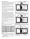
T&P Relief Valve and Pipe Insulation (Some Models)
1. Locate the T&P Relief Valve on the water heater.
2. Locate the slit running the length of the insulation.
3 Spread this slit open and slip it over the T&P Relief Valve.
See Figure 15B. Apply gentle pressure to the insulation
to ensure it is fully seated on the T&P Relief Valve. Once
sealed secure the insulation with a section of tape.
IMPORTANT: The insulation or tape should not block or
cover the T&P Relief Valve drain opening. Also the
insulation or tape should not block or hinder access to the
T&P Relief Valve manual relief lever.
4. Next locate the hot water (outlet) & cold water (inlet) pipes
to the water heater.
5. Select one of the sections of pipe insulation and locate the
slit that runs the length of the insulation.
6. Spread the slit open at the base of the insulation and slip
it over the cold water (inlet) pipe. Apply gentle
pressure along the length of the insulation to ensure it is
fully seated around the cold water pipe. Also ensure that
the base of insulation is flush with the water heater. Once
seated, secure the insulation with a section of tape.
7. Repeat steps 5 through 6 for the hot water (outlet) pipe.
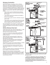
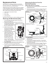
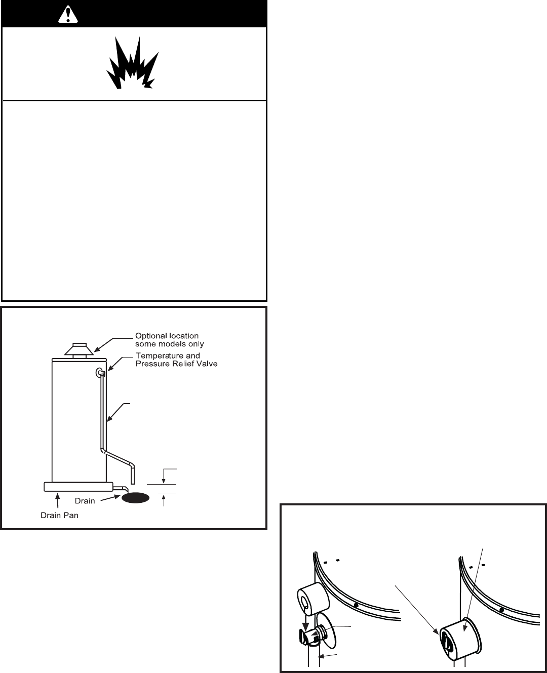
Figure 15A
Temperature and Pressure
Relief Valve Installation
Discharge line 3/4" minimum
Do not cap or plug.
6" maximum
Figure 15B
T&P Relief Valve Insulation
T&P Relief Valve
T&P Relief Valve
Drain Line
Manual Relief Lever
T&P Relief Valve Insulation
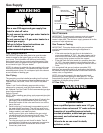
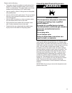
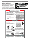
Explosion Hazard
If the temperature and pressure relief valve
is dripping or leaking, have a qualified
person replace it.
Examples of a qualified person include:
licensed plumbers, authorized gas company
personnel, and authorized service
personnel.
Do not plug valve.
Do not remove valve.
Failure to follow these instructions can
result in death, or explosion.
WARNING