


DOOR-WIDTH PLUS 3-3/8” (86 mm) TO 3-1/2”
(89 mm)
72”
(1829 mm)
3
d
d
30” TO 36” SPACING
13B
e
e
17
SET SCREW
18
CANOE
CLIP
2
6B
e
8B
e
16A
16B
16C
16D
f
f
h
20
12A
12B
12C
RIGHT HAND
DRUM
6C
e
CABLE
5/8”(16MM)
6A
6A
6B
6C
e
1-11/16” (43mm)
TO 1-3/4” (44mm)
LEFT HAND
DRUM
4
LEFT HAND
BOTTOM
BRACKET
MILFORD
PIN
HINGE
TUBE
ASTRAGAL
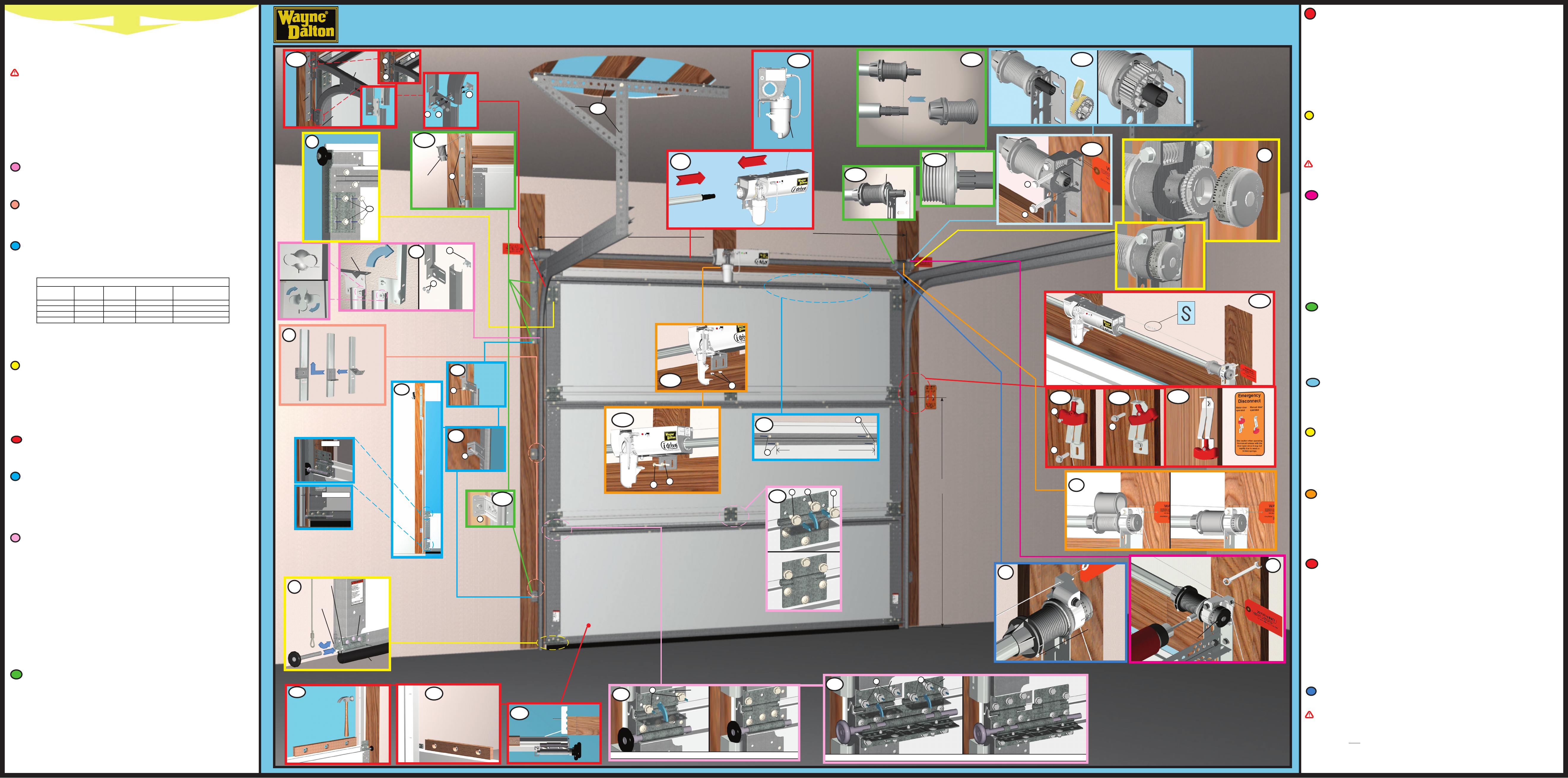
Beginning with the right side, install the counter gear with the missing tooth toward the outside, away from the end
bracket. Press the counter gear onto the end bracket until snaps engage. Select the right hand counter cover assembly and
align the hex of the counter cam with the end of the winding shaft. Also, align the “0” on the counter cover with the raised
rib on the end bracket. Press the counter cover assembly against the counter gear until it locks into place. Repeat for left
hand side for double spring applications.
NOTE: No drive gear, counter gear or counter cover assembly is required on left hand side for single spring applications.
Only an end bracket is needed.
IMPORTANT! At this time do not wind counter balance springs!
14
CONTINUE INSTALLATION INSTRUCTIONS ON REVERSE SIDE.
NOTE: For non-idrive™ operated garage doors see Alternate Installations on the reverse side of this manual.
NOTE: For idrive™ operated garage doors, refer to 302879 insert for replacing the standard motor cover with the
low headroom motor cover.
NOTE: Opener will not slide over a torque tube label.
Attempting to slide opener over the left end of the torque tube can damage the internal electronics.
NOTE: Hold opener by the main body. Do NOT hold by the motor.
NOTE: Do not force the opener onto the torque tube if misalignment occurs.
Continue sliding the opener power head onto the torque tube. Align the right hand bearing with the torque tube and slide
the opener power head completely onto the torque tube until the torque tube exits the opener power head’s right hand
bearing. Continue sliding the opener power head to the center of the torque tube and plug the motor power cord into
the opener power head.
IMPORTANT! Right and left hand is always determined from inside the garage looking out.
11 idrive™ Installation
12
Shake the torque tube gently to extend the winding shafts out about 5” on each side. For single spring applications,
together only one way. To install the cable drum, slide the drum over the winding shaft until the drum seats against the
torque tube. The winding shaft must extend past the drum far enough to expose the splines and the groove. Align the
single spring applications, insert the left hand loose winding shaft into the left hand drum prior to sliding the drum over
the torque tube.
NOTE:
back into the torque tube.
Beginning with the right hand side, lubricate entire circumference of the drive gear with the oil provided in the packet.
NOTE: No drive gear is required for the left side on single spring applications.
IMPORTANT! Warning tags must be securely attached to both end brackets.
13
Locate the spring pad. The spring pad is a vertical running board directly above the center of the door. Remove
NOTE:
Place the support bracket underneath opener power head, to the right side of motor, centered on spring pad. Level the
torque tube to the top of the door section with the idrive™ resting on the support bracket. Once torque tube is level,
NOTE:
15
16
both ends of “S” hook to lock assembly together. Thread the disconnect cable through hole in right hand end bracket
the ground to mount disconnect handle. Thread disconnect cable through handle bracket and then handle. Align top of
handle bracket with mark on wall. Remove all cable slack between the power head and top of handle bracket. Insert and
off excess cable from bottom of handle. Holding handle bracket, remove all remaining slack between power head. With
CAUTION: Pull handle just enough to remove the cable slack. Pulling the cable more could cause the opener power
head to disconnect from the torque tube.
Rotate disconnect handle to one side exposing upper mounting hole in handle bracket. Secure handle bracket with a
fasteners if adhesive will not adhere. Using the emergency disconnect, pull disconnect handle downwards and place it
in the manual door operated position. Use disconnect label for reference. Motor will be rotated 90° from its packaged
position.
NOTE: If motor does not pivot 90°, see troubleshooting section in the idrive™ main installation manual.
START HERE
TWISTLOCK HOLE
TWISTLOCK TAB
FULLY ADJUSTABLE
TRACK
a
Q.I. TRACK
FLAG
ANGLE
1
14
NOTE:’ high 3 section doors, and by the yellow and
black warning label attached to the right side of the section.
Insert rollers into both end stiles of the lock section, Fig. 7A. With assistance lift section and place rollers over the
tops of the vertical tracks. Install by guiding rollers into the vertical track on both sides and gently lowering the sec-
IMPORTANT! For larger size doors, double end hinges are already pre-installed to the section(s).
Double end hinges are installed by rotating both hinge leafs upward and secure the hinges to the above section
The center hinges are installed by rotating the hinge leaf upward and secure the hinge to the above section with
IMPORTANT! Push and hold both hinge leafs up against the section while securing with 1/4”-14x 5/8”
self tapping screws.
Do not install the top section at this time.
7
Q.I. agangle:
Fully adjustable agangle:
1
Measure the length of the vertical tracks. Using the Quick Install Jamb Bracket Schedule (shown on reverse
side),
is toward the back leg of the track. Set tracks aside.
2
NOTE: The stutting schedule below is for reference only, all struts are pre-installed at the factory.
3
Position the left hand vertical track over the rollers of the bottom section.
NOTE:
IMPORTANT! The tops of the vertical tracks must be level from side to side. If the bottom section was shimmed
to level it, then the vertical track on the shimmed side, must be raised the height of the shim.
6
-
bottom astragal, if necessary.
5
IMPORTANT! TITLED “REMOVING THE OLD DOOR/PREPARING THE OPENING”. IF THE
INSERT SHEET INSTRUCTIONS ARE NOT INCLUDED, CONTACT WAYNE-DALTON CORP. FOR A
FREE COPY.
If removing an existing door, carefully follow the directions given on the insert sheet instruction in the portion
titled “Removing the Old Door”.
WARNING!
SHEET INSTRUCTIONS CAREFULLY, OTHERWISE SEVERE OR FATAL INJURY COULD RESULT.
IMPORTANT! Stainless steel or PT2000 Coated lag screws MUST be used when installing center bearing
brackets, end bearing brackets, jamb brackets, operator mounting/support brackets and disconnect
brackets on treated lumber (preservative-treated). Stainless steel lag screws are NOT necessary when
installing products on un-treated lumber.
NOTE:
For proper opening preparation refer to the portion of the insert sheet instructions titled “Preparing the Opening”.
IMPORTANT! It is recommended that doors 12’ 0” wide and over be installed by two person, to avoid
possible injury.
9
FULLY ADJUSTABLE
TRACK
VERTICAL
TRACK
FLAG
ANGLE
HORIZONTAL
ANGLE
a
j
a
b
a
i
13A
19
i
LEFT HINGE SHOWN, RIGHT HINGE SYMMETRICALLY OPPOSITE
HINGE
LEAF
7A
d
7C
d
d
d
5500/9700 Estate - Low Headroom Front Mount -TorqueMaster™
Installation Instructions Layout
4
TorqueMaster™ drums are marked right and left. Make sure you place the cable from the right hand drum on the
right hand milford pin, and left hand drum on the left hand milford pin. Uncoil the counterbalance cables and slip
the loop at the ends of the cables over the milford pins on the bottom section. Insert a roller in the bottom bracket of
for right side.
NOTE:
bracket warning labels on each endstile.
NOTE:
trimmed off, be careful not to stretch astragal, or it may end up shorter than section width.
IMPORTANT! Right and left hand is always determined from inside the building looking out.
8A
d
10
To install low headroom horizontal track, align the bottom curve of the horizontal track with the top of the vertical
track.
Q.I. agangle:
Push the curved portion of the horizontal downward to lock into place.
Fully adjustable agangle :
NOTE:
9
To install the low headroom top brackets, align the top slots in the low headroom top brackets with the third set of holes
nail that was temporarily holding the top section in place.
IMPORTANT! Failure to remove nail before attempting to raise door could cause permanent damage to top
section.
WARNING!
DO NOT RAISE DOOR UNTIL HORIZONTAL TRACKS ARE SECURED AT REAR, AS OUTLINED IN STEP 20,
10
8
IMPORTANT! Operator bracket must be installed before strut (if applicable) are attached to the top section.
See optional accessory on the reverse side of this manual (operator bracket).
Place top section in the door opening and secure it temporarily by driving a nail into the header near the center of
the door and bending it over the section. Now fasten the hinges to the top section, Fig. 7A thru 7C. When installing a
IMPORTANT! The dimension between the agangles must be door-width plus 3-3/8” (86mm) to 3-1/2” (89
mm) for smooth, safe door operation.
STRUTTING SCHEDULE
DOOR WIDTH QUANTITY
TOP OF TOP
SECTION
TOP OF LOCK
SECTION
TOP OF BOTTOM
SECTION
6’ 0” TO 10’ 11”
0 N/A N/A N/A
11’ 0” TO 14’ 2”
1X N/A N/A
14’ 3” TO 16’ 2”
2X N/A X
16’ 3” TO 18’ 0”
3X XX
17
winding counterbalance springs.
WARNING!
FAILURE TO CLAMP TRACK CAN ALLOW DOOR TO RAISE AND CAUSE SEVERE OR FATAL INJURY.
IMPORTANT! Do NOT double wrap counterbalance cables on TorqueMaster drums.
Cut off excess cable.
8B
HINGE LEAF
d
d
LEFT HINGE SHOWN, RIGHT HINGE SYMMETRICALLY OPPOSITE
HINGE
LEAF
11B
11A
LOW HEADROOM
MOTOR COVER
15A
g
g
15B
a