


9
107031
OWNER’S MANUAL
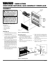
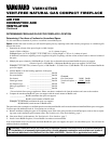
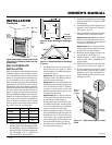
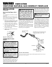
Figure 8 - Mounting Clearances As Viewed
From Front of Fireplace Shown with Op-
tional Mantel
Top Of
Mantel Can
Be Flush
With Wall
Left
Side
CEILING
Right
Side
36"
Minimum
INSTALLATION
Continued
Continued
36 5/8"
25 7/8"
51 3/4"
26 7/8"
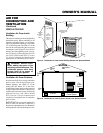
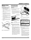
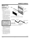
Figure 10 - Rough Opening for Installing
in Corner
1. Frame in rough opening. Use dimensions
shown in Figure 9 for the rough opening.
If installing in a corner, use dimensions
shown in Figure 10 for the rough open-
ing. The height is 26
7
/8" which is the
same as the wall opening above.
26 7/8"
26 7/8"
3/4" Off
The Floor
Minimum
10 1/2"
Figure 9 - Rough Opening for Installing in
Wall
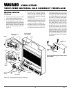
BUILT-IN FIREPLACE
INSTALLATION
Built-in installation of this fireplace involves
installing fireplace into a framed-in enclo-
sure. This makes the front of fireplace flush
with wall. An optional brass trim kit acces-
sory is available (see Accessories, page 27).
Brass trim will extend past sides of fireplace
approximately 1/2 inch. This will cover the
rough edges of the wall opening. If install-
ing a built-in mantel above the fireplace, but
you must follow the clearances shown in
Figure 12, page 10. Follow the instructions
below to install the fireplace in this manner.
Note:
Your Vanguard fireplace is designed
to be used in zero clearance installations.
Wall or framing material can be placed
directly against any exterior surface on the
rear, sides, or top of your fireplace.
Actual Framing
Height 26" 26
7
/8"
Front Width 26
3
/4" 26
7
/8"
Depth 9
1
/2" 10
1
/2"
Bottom 3/4" 3/4"
2. An optional blower accessory is avail-
able (see Accessories, page 27). There
are three options for connecting blower
to electrical source.
Option one: Install fireplace near an
electrical outlet. See Blower Instruc-
tions for power cord length.
Option two: Have a licensed electrician
install a properly grounded, three-prong
120-volt electrical outlet at fireplace
location. Locate outlet inside the
framed enclosure. Blower power cord
will plug into this outlet.
Option three: Have a licensed electri-
cian connect blower to electrical source
at junction box inside fireplace.
If using option one, have electrical out-
let installed at this time. If using option
two, do not connect blower to electrical
source at junction box until step 7.
3. Install gas piping to fireplace location.
This installation includes an approved
flexible gas line (if allowed by local
codes) after the equipment shutoff
valve. The flexible gas line must be the
last item installed on the gas piping.
4. If you have not assembled firebox, fol-
low instructions on page 4.
5. Carefully set fireplace in front of rough
opening with back of fireplace inside
wall opening.
6. Attach flexible gas line to fireplace gas
regulator. See Connecting Fireplace to
Gas Supply, page 15.
7. If the optional blower has been installed
connect blower to electrical source.
Options one and two: Route blower
electrical cord through side or rear ac-
cess door of fireplace. Plug electrical
cord into electrical outlet.
Option three: Have a licensed electri-
cian connect blower to electrical source
at junction box inside fireplace.
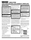
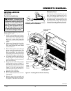
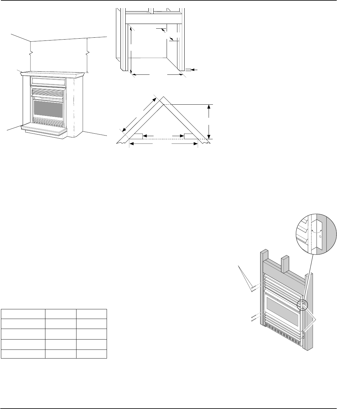
8. Bend four nailing flanges on outer cas-
ing with pliers (see Figure 11).
9. Attach fireplace to wall studs using
nails or wood screws through holes in
nailing flange.
10. Check all gas connections for leaks. See
Checking Gas Connections, page 16.
11. If using optional brass trim kit, install
the trim after final finishing and/or
painting of wall. See instructions in-
cluded with brass trim accessory for at-
taching brass trim.
Figure 11 - Attaching Fireplace to Wall
Studs
Nailing
Flanges
Nails or
Wood
Screws